
 | ||
A fault model is an engineering model of something that could go wrong in the construction or operation of a piece of equipment. From the model, the designer or user can then predict the consequences of this particular fault. Fault models can be used in almost all branches of engineering.
Contents
Basic fault models
Basic fault models in digital circuits include:
Fault assumption
A fault model, falls under one of the following assumptions:
Fault collapsing
There are two main ways for collapsing fault sets into smaller sets.
Equivalence collapsing
It is possible that two or more faults produce same faulty behavior for all input patterns. These faults are called equivalent faults. Any single fault from the set of equivalent faults can represent the whole set. In this case, much less than k×n fault tests are required for a circuit with n signal line. removing equivalent faults from entire set of faults is called fault collapsing. fault collapsing significantly decreases the number of faults to check.
In the example diagram, red faults are equivalent to the faults that being pointed to with the arrows, so those red faults can be removed from the circuit. In this case, the fault collapse ratio is 12/20.
Dominance collapsing
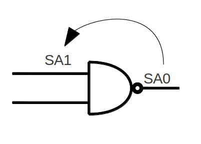
Fault F is called dominant to F' if all tests of F' detects F. In this case, F can be removed from the fault list. If F dominates F' and F' dominates F, then these two faults are equivalent.
In the example, a NAND gate has been shown, the set of all input values that can test output's SA0 is {00,01,10}. the set of all input values that can check first input's SA1 is {01}. In this case, output SA0 fault is dominant and can be removed from fault list.
Functional collapsing
Two faults are functionally equivalent if they produce identical faulty functions or we can say, two faults are functionally equivalent if we can not distinguish them at primary outputs (PO) with any input test vector.
Fault models in Aerospace contexts
A fault model in an Aerospace context is a set of structured information which helps users or systems to identify and isolate a problem that occurs on an engine, Line-replaceable unit (LRU), or Auxiliary power unit (APU) during a flight. Associated with this fault model may be a suggested repair procedure along with references to Aircraft maintenance manuals (~ Light maintenance manual).