
 | ||
The Fabric of Security , also known as Cyber Security Fabric or Federated Security, refers to systems designed to protect the Information Systems infrastructure of the home, a corporation or government from malicious attackers. Protection in this sense means, guaranteeing the confidentiality, integrity, and the availability of the information stored in the system ("SYSTEM"), and its elements or components.
Contents
- Security essentials
- Lampsons Protection Model
- Fabric of security principles and architecture
- FOSA Architecture
- Description of the FOSA Architecture
- References
Unlike endpoint security, network security, web application security, and Internet security, Fabric of Security Systems assume that attacks will be successful, and cannot be averted. Therefore, the emphasis shifts from attempting to prevent unauthorized access to that of minimizing the time to detect the unauthorized access, the time to isolate the unauthorized access from doing harm, and finally, the time to remove the offending process and reconfiguration of the system back into a "SAFE" state.
Security essentials
Security refers to processes and systems designed to protect the assets of an individual, system and/or organization from harm. Computer Security (aka, cyber security) refers to processes and systems designed to protect computer and/or information system assets from harm. In general, such assets are: (1) information/ data, (2) programs and applications, and (3) services. Protecting assets from harm means:
Confidentiality – assets are used/access only by authorized parties (also refer to as secrecy or privacy)
Integrity – assets can be modified only by authorized parties and only in authorize ways (“insider threat”)
Availability – assets are available to authorize parties at time to.
Lampson's Protection Model
In 1971 Butler Lampson in his now classical paper Protection introduced the general model of protection of computer or information system assets which has withstood the passage of time. By enlarge, all protection systems implemented to date follow Lampson's original formulation shown here in Figure 1 entitled "Access Control Model of Protection". Fundamentally the universe is divided into two classes Principals, who access Resources. A Resource is an object for which a protection policy has been established. Access to Objects is restricted via a protection system, called a reference monitor, that implements the protection policies of the system. Namely the reference monitor or "Guard System" must: (1) identifies the identity of the Principal claiming access to an object - Principal is who are you?, (2) authentication - validates that the Principal claiming access to an object is who he/she/it claims to be - are you who you say you are?, and (3) authorization - is the principal claiming access to an object authorized to access said object.
Fabric of security principles and architecture
In the past, the protection model that most organizations applied to protect their infrastructure was simply the "Everything but the Kitchen Sink" model—meaning, add devices that protect the enterprise network perimeter (Trusted Zone), add devices that protect your mobile device, add devices that protect your database. In essence, this model simply advocated for the accumulation of security devices. As we pointed out earlier, see section 1.0, this model has failed.
In addition, the idea that cyber-attacks can be stopped at the periphery of the network has become a fool's errand. In today's Circa 2020 computing environment and cyber-threat landscape, individuals as well as corporations have recognized the fact that (i) threats are often distributed in nature both in time and space, making detection extremely difficult, and (ii) the working assumption is not that you can prevent infections (the goal of 100% prevention is no longer practical), but rather, given that your "system" will be compromised, how quickly can you detect the breach and how do you minimize the impact of such an event? In the future, the basis of competition for security products and services will be the ability to provide early warnings and execute countermeasures that minimize damage from cyber-attackers. The problem is not about single or even multiple independent security devices each providing some amount of absolute protection. Rather, information from all your security products and services need to be correlated, scrutinized and transformed into wide-angle actionable information in order to minimize the most likely threats of damage by cyber-attackers in your specific enterprise environment, see Figure 3. We call this approach the “Fabric of Security.” It is a layered model that easily accommodates distributed deployment of security in multi-vendor environments.
FOSA Architecture
In 2013, the Wireless Systems Security Research Laboratory (WSSRL) started the development of a first-reference implementation of the Fabric of Security called FOSA. The purpose of FOSA was to use proven techniques from the areas of distributed processing, computer architecture and clustering algorithms, to build a viable, real-time security system capable of protecting the corporate infrastructure of the Circa 2020 computing model. FOSA was intended to be the first implementation of the Fabric of Security architecture, while at the same time remedying some of the limitations of current security system implementations. Specifically, the stated goal for the design was to avoid stand-alone solutions while incorporating the ability to deal with reliability issues, meaning, the best security product/solution is no good if either it fails to operate as specified (Fault Tolerant) and/or is compromised by the attacker (Resilient to Attacks). It must be able to withstand attacks directly against itself, and be able to protect itself from being compromised or disabled.
Description of the FOSA Architecture
In this section, we provide a brief overview of the FOSA system and its major components. However, in this manuscript we will not cover the reliability and adaptability elements of the architecture, and the use of Byzantine Agreement, see [4], to build resiliency into the system.
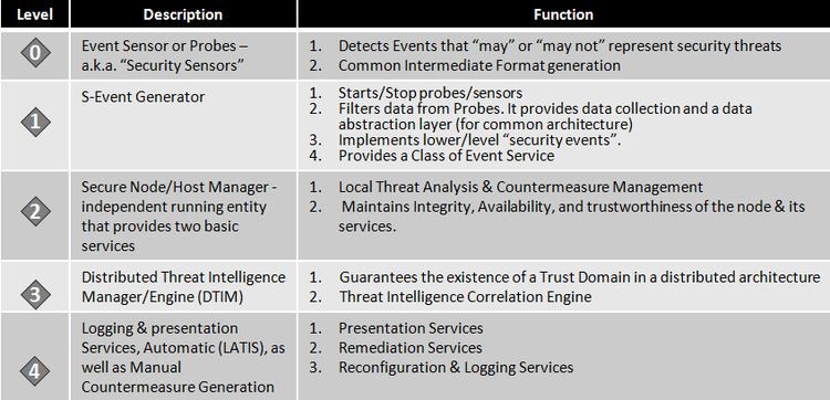
The architecture of FOSA is shown here in Figure 4. FOSA is a distributed system based on layer component architecture. In each FOSA node, a set of components in a hierarchical structure provide the traditional security functions found in most implementations. At the lowest level of the hierarchy, Layer0, we find the traditional data gathering component or SENSORS/Probes. Unlike other systems, SENSORS in FOSA can be custom data collectors or simply gather data from other security systems, such as FIREWALLS, and AV systems. In the latter case, SENSORS gather the data by monitoring the output of a variety of systems outputs, such as Snort, and the syslog file on Linux. The data collected by the SENSORS serve as input to the next layer in the hierarchy, Layer1, the S-Event Generator or SEG. The SEGs function as a data abstraction layer. They collect the data from the SENSORS, filter it, convert it into a platform independent format, and provide the aggregated, filtered data to the next layer of the hierarchy, the Secure Host Manager or SHM in the form of events. The events are queued for further analysis by the SHM. In addition to this, the SEGs start and stop the SENSORS. In this context, the SHM can be consider as the local IDS/IPS that makes decisions about all activities that it monitors both host- or network-based. A critical component of the SHM is the Analysis Engine AE. The AE retrieves events from the Event Queue, processes them, and makes a final determination as to the probability that a successful attack will be launched, and/or an attack is in progress at the local level. This probability falls into one of three ranges. These are:
0 ≤ p{Attack in Progress or a Compromise has occurred } ≤ Φ1 - No ATTACK
Φ1 ≤ p{ Attack in Progress or a Compromise has occurred } ≤ Φ2 - There is insufficient data at the local level to make a decision. In addition, in some situations this is an indication that the local node has been compromised.
Φ2 ≤ p { Attack in Progress or a Compromise has occurred } - ATTACK detected
In the first case, the SHM is sure that the events processed do not represent an attack or elements of an Attack, and therefore the system continues operation without further actions. However, in the next two cases a potential attack has taken place or is in progress. In such a case, the SHM immediately initiates countermeasures. The first of which is to stop all further processing of events, disable all remote access to the node, and notify the next level of the hierarchy, the Distributed Threat Intelligence Manager/Engine (DTIM), that a potential failure or attack is in the making. Further, in the case that the SHM is sure the host has been compromised, then, the SHM also sends a “last gasp” message to the DTIM. Once it sends the “last gasp” message, the SHM stops the SEGs, stops processing data from the SEGs and launches countermeasures to restore the node to a healthy state.
2.1.2 Distributed Threat Intelligence Manager/Engine (DTIM)
As previously mentioned, FOSA is a real-time, distributed system based on the concept of autonomous agents. Its structure is similar to the architecture proposed in the AAFID system. However, it differs from it in at least three significant ways. These are:
- It is fault resilient. It can protect itself from traditional hardware and software failures, as well as malicious attacks.
- It has a learning engine capable of integrating new knowledge into its decision matrix.
- Attack Detection/ Prevention occurs at two levels. At the local level, SHM represents the traditional IDS/IPS system. However, decisions that affect the health of the entire system, or decisions concerning a distributed attack, are made by correlating information among all security devices in the system using a Byzantine Agreement Protocols or BAP.
In the architecture, the Distributed Threat Intelligence Engine/Manager (DTIM) consists of two major components: (1) the Distributed Trust Manager (DTM) which performs the critical functions of Fault Tolerance and Attack Resilience, and (2) the Distributed Threat Intelligence Correlation Engine (TICE) that performs the function of Threat and Event detection globally.
2.1.2.1 Distributed Trust Manager (DTM)
The DTM performs several essential functions. These are:
The creation of a Trust Domain and the formation of an initial group have been discussed in a previous work, see [2] in detail. However, because nodes can be compromised and their status can change over time, the DTIM must have the capability of expelling members and reconfiguring itself. This process of reconfiguration is initiated by either the receipt of a “last gasp” message from a member or when the DTM reconfiguration timer expires. The basic process works as follows. Upon receipt of a “last gasp” message, every node in the Trust Domain will initiate the reconfiguration by: • Sending a set of test patterns to the node suspected of being compromised. The test pattern matrix consists of a set of known intrusion vectors, as well as a set of non-intrusion patterns. Upon formation of the initial group, and every time that membership in the Trusted Domain changes, the matrix is reconstituted and distributed among all members. The matrix is distributed in such a way that no single member group of members colluding (as long as k, k N-1)/ 2; where k is number of colluding members), has complete knowledge of all test patterns
2.1.2.2 Distributed Trust Manager component of the DTIM in FOSA- An Abstract Model
One of the key components of the Distributed Threat Intelligence Manager/Engine is the Distributed Trust manager of DTM. The DTM is built upon the principles of replication, consensus, and the ”wisdom of crowds.” In order to understand the behaviors of the FOSA system, it is important that an abstract model of the Trust Domain (TD) is presented. Here we present such a model. Let M = {C, Cnew, P, X, α}, be an abstract representation for a Trust Domain. This model allows us to reason as to the correctness of the DTM component of the Threat Intelligence/Engine. One potential side benefit of the model is that it will allow us to identify holes in our design. The basic components of the model, C, P, X, and α are defined below. C = {c1, c2, c3, ..., cn}, for some finite integer n, is the set of nodes in the Trust Domain. A node within this context is any Security Device that is collecting data and making decisions about the possibility of an attack. While n could be very large, for practical purposes associated with the implementation of DTM, we limit n to 16.
cnew = cj |cj ∈/ C, which is a node that is trying to join a Trust Domain. The state, w, of cnew is unknown at the time that cnew declares its intention to join a Trust Domain. That is, cnew may be a node whose behavior is in accordance with the Trust Domain admission and security policies (“uncompromised node”) or it may be compromised.
α = {α1, α2, α3, ..., αm} is the set of actions that a node may perform. A node is essentially a deterministic finite automaton. Thus, it has a finite set of states, a finite set of input symbols and a transition function [3]. The transition function is analogous to the set of actions a node may take based on the input the node receives. Since the input alphabet is finite and the number of states is finite, the set of actions, α, which a node may take, is finite.
P = {p1, p2, p3, ..., pk} is a security policy which describes the acceptable behaviors of a Security Device in the Trust Domain. Each pi is a rule composed of a subject, an object and an action that the subject may perform on the object. We note that security policies are rarely defined completely, as it is difficult to list every possible rule that is acceptable. Thus, we accept that we will have to add new rules to the policy as new acceptable actions that a node may perform on an object are discovered. It should be clear that P ⊆ α. We also note that ¬P ∪ P = α.
X is a capability matrix, which indicates what actions the subjects can perform on the objects and/or on each other. The subjects here are the nodes. The objects are the data and the services running on the nodes. Xij represents all the actions that subject subjecti can perform on object objectj . In other words, for each object oj on computer nodek, Xij gives the set of actions, αl ∈ α that computer nodek can execute on behalf of subjecti on object 0j .
Using this model, we defined a capability and policy matrix for our experimental Trust Domain, see Figure 5, with corresponding security policy P ={p1, p2, p3, ..., pk } below.
2.1.2.3 Security Policy
We define several variables and constants that are necessary to define the security policy, P. The variables are:
OSi =the current operating version on nodei FOSAi = FOSA software version nodei responsei,x = the response nodei gives to nodex in the TD when it is interrogated opinioni,x = the belief of nodex in the TD about whether nodei is compromised majorityi,x = the majority belief of all the nodes in the TD about whether nodei is com- promised after the parallel Signed Message Algorithm has been completed messageTamperedi = whether messagei has been tampered with
The constants present in the security policy are:
OST = the minimum acceptable O/S version for a node to join the TD FOSAT = the minimum acceptable version of the FOSA software responsec = the correct response of a node to an interrogation compromised = the majority belief that the node trying to join the TD is compromised uncompromised= the majority belief that the node trying to join the TD is safe
Using this model, we defined a capability and policy matrix for our experimental Trust Domain, see Figure 5. The corresponding security policy P ={p1, p2, p3, ..., pk } is defined below. Based on these definitions, the security policy can be described as follows:
p1: Given a node, ci ∈ Cnew, that is attempting to join a TD, then, if the value of OSi < OST, then ci is not allowed to join TD
p2: Given a node, ci ∈ Cnew, that is attempting to join a TD, then, if the value of SAFEi < SAFET, then ci is not allowed to join TD
p3: Given a node, ci ∈ Cnew, that is attempting to join a TD, and a node cx in the TD, then, if the value of responsei,x = responsec, then opinioni,x = compromised
p4: Given a node, ci ∈ Cnew, that is attempting to join a TD, and a node cx in the TD, then, if the value of responsei,x = responsec, then opinioni,x = uncompromised
p5: Given a set of nodes, c1, ..., cx, in a TD, a node ci not in TD, and a majorityi,x = compromised, then, cx does not open a socket connection to ci (preventing ci to join TD).
p6: Given a set of nodes, c1, ..., cx, in a TD, a node ci not in TD, and a majorityi,x = uncompromised, then, cx opens a socket connection to ci (thus allowing ci is to join TD).
p7: Given nodes cx and cy are nodes in a TD, and cx receives messagei from cy, such that messageTamperedi = T rue, then, cx discards messagei as if it was never received.
2.1.3 Threat Intelligence Correlation Engine (TICE)
TICE or the Threat Intelligence Correlation Engine is a global engine whose inputs are the events generated by the SHM module at a lower level of the hierarchy, local information as to the configuration of the environment under protection, global information as to the current threat level in the particular region and the corresponding and pertinent threat landscape at the time of the events. The output of TICE is threat evaluations, actionable intelligence, and threat countermeasure recommendations. Similar to its lower level counterparts at Layer2 - the SHM, TICE evaluates & correlates events and ascertains the correlation of such events into three distinct possibilities:
0 ≤ p{Attack in Progress or a Compromise has occurred } ≤ Φ1 - No ATTACK/Intrusion
Φ1 ≤ p{ Attack in Progress or a Compromise has occurred } ≤ Φ2 - Insufficient Data
Φ2 ≤ p { Attack in Progress or a Compromise has occurred } - Attack/ Intrusion present The values of Φ1 and Φ2 are tunable.
2.1.4 Logging and Presentation Services - Issuance of Countermeasures (LAPIS)
LAPIS represents the top layer of the architecture, and it is the module where actionable intelligence is presented to an administrator for further action and/or where automatic countermeasures are issued throughout the protected environment. In the simplest implementation of the FOSA architecture, LATIS is the equivalent of a Security Information and Event Management (SIEM) module. It provides visual information to the security officer/administrator as to the state, real time threats that have been detected and the overall integrity of the protected environment.
Typical SIEM capabilities such as: (1) Security Event Management (SEM), (2) File Integrity Monitoring (FIM), (3) Configuration Management Database (CMDB), and (4) Availability and Performance Monitoring (APM) are part of this layer. However, unlike your typical SIEM, the LAPIS layer provides for automatic countermeasure generation, repair and recovery, as well as manual mode where forensics and countermeasure issuance is based on a probabilistic model with tunable Φ1 and Φ2 parameters.