Neha Patil (Editor)

Evolution from Francis Turbine to Kaplan Turbine

Updated on
Edit
Like
Comment
Share on FacebookTweet on TwitterShare on LinkedInShare on Reddit
Evolution from Francis Turbine to Kaplan Turbine

Francis turbine converts energy at high pressure heads which are not easily available and hence a turbine was required to convert the energy at low pressure heads, given that the quantity of water was large enough. It was easy to convert high pressure heads to power easily but difficult to do so for low pressure heads. Therefore, an evolution took place that converted the Francis turbine to Kaplan turbine, which generated power at even low pressure heads efficiently.

Contents

Changes

Turbines are sometimes differentiated on the basis of the type of inlet flow, whether the inlet velocity is in axial direction, radial direction or a combination of both. Francis turbine is a mixed hydraulic turbine (the inlet velocity has Radial and Tangential Components) while the Kaplan turbine is an Axial hydraulic turbine(the inlet velocity has only Axial Velocity Component). The evolution consisted of the change in the inlet flow mainly.

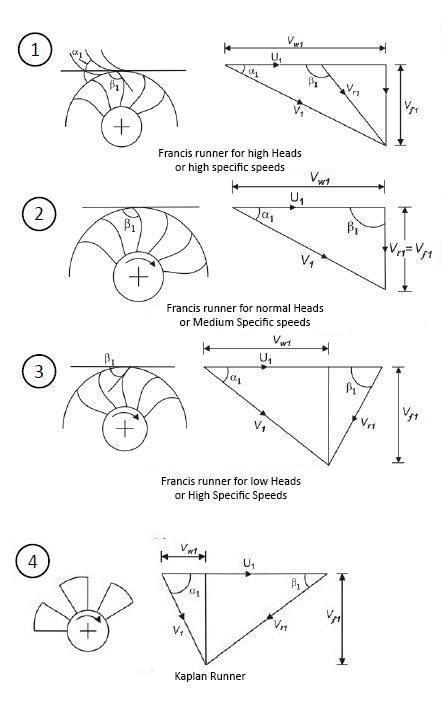
Nomenclature of a Velocity Triangle:

A general velocity triangle consists of the following vectors:

  • V : Absolute velocity of the fluid.
  • U : Tangential velocity of the fluid.
  • Vr: Relative velocity of the fluid after contact with rotor.
  • Vw: Tangential component of V (absolute velocity), called Whirl velocity.
  • Vf: Flow velocity (axial component in case of axial machines, radial component in case of radial machines).
  • α: Angle made by V with the plane of the machine (usually the nozzle angle or the guide blade angle).
  • β: Angle of the rotor blade or angle made by relative velocity with the tangential direction.
  • Generally, the Kaplan turbine works on low pressure heads (H) and high flow rates (Q). This implies that the Specific speed (Ns) on which Kaplan turbine functions is high as Specific speed (Nsp) is directly proportional to Flow (Q) and inversely proportional to Head (H). On the other hand, Francis turbine works on low Specific speeds i.e., high pressure heads.

    In the figure, it can be seen that the increase in Specific speed (or decrease in Head) have following consequences:

  • A reduction in inlet velocity V1 .
  • The flow velocity Vf1 at inlet increases, and hence allows a large amount of fluid to enter the turbine.
  • Vw component decreases as moving to Kaplan turbine, and here in the figure, Vf represents axial (Va) component.
  • The flow at inlet, in the figure, to all the runners, except the Kaplan impeller, is in radial (Vf)and tangential (Vw) directions.
  • β1 decreases as the evolution proceeds.
  • However, the exit velocity is axial in Kaplan runner, while it is the radial one in all other runners.
  • Hence, these are the parameter changes that has to be incorporated in converting a Francis turbine to Kaplan turbine.

    General differences between Francis and Kaplan turbines

  • Efficiency of Kaplan turbine is higher than Francis turbine.
  • Kaplan turbine is more compact in cross-section and has lower rotational speed to that of Francis turbine.
  • In Kaplan turbine, the water flows axially in and axially out while in Francis turbine it is radially in and axially out.
  • The runner blades in the Kaplan turbine are less in number as the blades are twisted and covers a larger circumference.
  • Friction losses in Kaplan turbine are less.
  • References

    Evolution from Francis Turbine to Kaplan Turbine Wikipedia