
 | ||
Event partitioning is an easy-to-apply systems analysis technique that helps the analyst organize requirements for large systems into a collection of smaller, simpler, minimally-connected, easier-to-understand "mini systems" / use cases.
Contents
Overview
The Event partitioning approach is explained by Stephen M. McMenamin and John F. Palmer in Essential Systems Analysis. A brief version of the approach is described in the article on Data Flow Diagrams. A more complete discussion is in Edward Yourdon's Just Enough Structured Analysis. The description focuses on using the technique to create data flow diagrams, but it can be used to identify use cases as well.
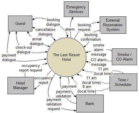
The premise of event partitioning is that systems exist to respond to external events: identify what happens in the business environment that requires planned responses, then define and build systems to respond according to the rules of the business. In particular, a business system exists to service the requests of customers. A customer, in the jargon of the Unified Modeling Language (UML), is an "actor".
Actor → Event → Detect → Respond
The method has the following steps.
The technique was extended with "non-event" events by Paul T. Ward and Stephen J. Mellor in Structured Development for Real-Time Systems: Essential Modeling Techniques.
Data dictionary notation
Yourdon/DeMarco style of data dictionary notation may be used to describe the composition and structure of data.
It is worth noting that the data structure elements can map to structured programming′s control structures:
NB. The items defined may be "material" (e.g., room key) as well as "data" (e.g., arrival date-time).
Identifying Requirements and Their Reasons
The event-response information may be captured in a table. The event is the raison d’être for the response, which gives "traceability" from the response back to the environment.
Defining requirements
This approach helps the analyst to decompose the system into "mentally bite-sized" mini-systems using events that require a planned response. The level of detail of each response is at the level of "primary use cases". Each planned response may be modelled using DFD notation or as a single use case using use case diagram notation.
The basic flow within a process or use case can usually be described in a relatively small number of steps, often fewer than twenty or thirty, possibly using something like "structured English". Ideally, all of the steps would be visible all at once (often a page or less). The intention is to reduce one of the risks associated with short-term memory, namely, forgetting what is not immediately visible ("out of sight, out of mind").
Alternatively, using the notations of structured techniques, an analyst could create a "Nassi–Shneiderman diagram". In the UML, the use case could be modelled using an activity diagram, a sequence diagram, or a communication diagram. This could be problematic if there are many complex scenarios of the use case; the analyst may wish to model all or most of the scenarios.
Complexity versus fragmentation
If the response is lengthy or complex (i.e., more than a page of text), an analyst may decompose ("factor out" or deduplicate) into smaller "secondary use cases" to keep the "parent" primary use case smaller and simpler. These secondary use cases may prove to be reusable as well. (In a UML use case diagram, they would be drawn as extended or included use cases, which are related to one or more primary use cases.)
While describing a use case, an analyst may also uncover "business rules". Some analysts suggest capturing business rules in a separate document using the Object Constraint Language or some other formal notation. Then when a business rule must be obeyed in a use case, the analyst makes reference to it. This minimises repetition within a specification, but risks fragmentation of a specification. One technique that may reduce this tension is to use hyperlinks in the specification document.
This reductionist approach lies somewhat in contrast to a systems thinking approach as represented by Peter Checkland's soft systems methodology.
In addition to functional requirements captured in a use case description, an analyst may include such non-functional requirements as response time, learnability, etc.