
 | ||
In fluid dynamics, the entrance length is the distance a flow travels after entering a pipe before the flow becomes fully developed. Entrance length refers to the length of the entry region, the area following the pipe entrance where effects originating from the interior wall of the pipe propagate into the flow as an expanding boundary layer. When the boundary layer expands to fill the entire pipe, the developing flow transitions to fully developed flow, where flow characteristics no longer change with increased distance along the pipe. Many different entrance lengths exist for a variety of flow conditions. Hydrodynamic entrance length describes the formation of a velocity profile caused by viscous fources propagating from the pipe wall. Thermal entrance length describes the formation of a temperature profile. Awareness of entrance length may be necessary for the effective placement of instrumentation, such as fluid meters.
Contents
- Hydrodynamic Entrance Length
- Boundary layer
- Shear stress w displaystyle au w
- Entry Length
- Entry Length For Pipes with Non circular Cross Section
- Average velocity
- Thermal Entrance Length
- Laminar Flow
- Turbulent Flow
- Heat Transfer
- Thermally Fully Developed Flow
- Applications
- Flow Meters
- Wind Tunnels
- Exit Length
- References
Hydrodynamic Entrance Length
The hydrodynamic entrance region refers to the area of a pipe where fluid entering a pipe develops a velocity profile due to viscous forces propagating from the interior wall of a pipe. This region is characterized by a non-uniform flow. The fluid enters a pipe at a uniform velocity, then fluid particles in the layer in contact with the surface of the pipe come to a complete stop due to the no-slip condition. Due to viscosity of the fluid, the layer in contact with the pipe surface, resists the motion of adjacent layers and slows them down gradually. For the conservation of mass to hold true the velocity of middle layers of the fluid in the pipe increases (since the layers of fluid near the pipe surface have reduced velocities). This develops a velocity gradient across the cross section of the pipe.
Boundary layer
The layers in which the shearing viscous forces are significant, is called boundary layer. This boundary layer is a hypothetical concept. It divides the flow in pipe into two regions:
- Boundary layer region: The region in which viscous effects and the velocity changes are significant.
- The irrotational (core) flow region: The region in which viscous effects and velocity changes are negligible.
When the fluid just enters the pipe, the thickness of the boundary layer gradually increases from zero moving in the direction of fluid flow and eventually reaches the pipe center and fills the entire pipe. This region from the entrance of pipe to the point where the boundary layer covers the entire pipe is termed as the hydrodynamic entrance region and length of the pipe in this region is termed as the hydrodynamic entry length. In this region the velocity profile develops and thus the flow is called the hydrodynamically developing flow. After this region, the velocity profile is fully developed and continues unchanged. This region is termed the (hydrodynamically) fully developed region. But this is not the fully developed fluid flow until the normalised temperature profile also becomes constant.
In case of laminar flow, the velocity profile in the fully developed region is parabolic but in the case of turbulent flow it gets a little flatter due to vigorous mixing in radial direction and eddy motion.
The velocity profile remains unchanged in the fully developed region.
Hydrodynamic Fully Developed velocity profile :
(where
Shear stress ( τ w ) {displaystyle ( au _{w})}
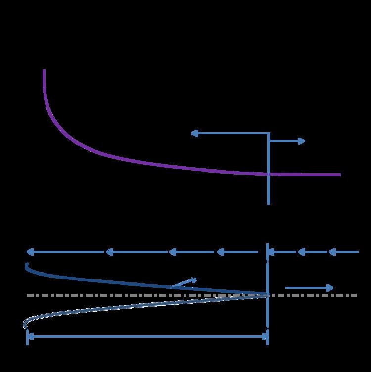
In the hydrodynamic entrance region, the wall shear stress (τw ) is highest at the pipe inlet where the boundary layer thickness is the smallest and it decreases along the flow direction. That is why the pressure drop is the highest in entrance region of a pipe and hence it always increases the average friction factor for the whole pipe. This increase in the friction factor is negligible for long pipes.
In fully developed region the pressure gradient and the shear stress in flow are in balance.
Entry Length
The length of the hydrodynamic entry region along the pipe is called the hydrodynamic entry length. It is a function of Reynolds number of the flow. In case of laminar flow, this length is given by:
Where,
But in the case of turbulent flow,
Thus, the entry length in turbulent flow is much shorter as compared to laminar one. In most practical engineering applications, this entrance effect becomes insignificant beyond a pipe length of 10 times the diameter and hence it is approximated to be :
Other authors give much longer entrance length, e.g.
Entry Length For Pipes with Non-circular Cross-Section
In case of a non-circular cross- section of a pipe, the same formula can be used to find the entry length with a little modification. A new parameter “hydraulic diameter” relates the flow in non-circular pipe to that of circular pipe flow. This is valid until the cross sectional area shape is not too exaggerated. Hydraulic Diameter is defined as:
Where,
Average velocity
By doing a force balance on a small volume element in the fully developed flow region in the pipe (Laminar Flow), we get velocity as function of radius only i.e. it does not depend upon the axial distance from the entry point. The velocity as the function of radius comes out to be:
Where
By definition of Average velocity,
Thus,
In a fully developed flow, the maximum velocity will be at r=0.
Thus,
Thermal Entrance Length
The thermal entrance length describes the distance for incoming flow in a pipe to form a temperature profile of stable shape. The shape of the fully developed temperature profile is determined by temperature and heat flux conditions along the inside wall of the pipe, as well as fluid properties.
Laminar Flow
For laminar flow, the thermal entrance length is a function of pipe diameter and the dimensionless Reynolds number and Prandtl number.
where:
The Prandtl number modifies the hydrodynamic entrance length to determine thermal entrance length. The Prandlt number is the dimensionless number for the ratio of momentum diffusivity to thermal diffusivity. The thermal entrance length for a fluid with a Prandtl number greater than one will be longer than the hydrodynamic entrance length, and shorter if the Prandtl number is less than one.
Turbulent Flow
For turbulent flows, thermal entrance length may be approximated solely based on pipe diameter.
where:
Heat Transfer
The development of the temperature profile in the flow is driven by heat transfer determined conditions on the inside surface of the pipe and the fluid. Heat transfer may be a result of a constant heat flux or constant surface temperature. Constant heat flux may be caused by joule heating from a heat source, like thermal tape, wrapped around the pipe.
Newtons law of cooling describes convection, the main form of heat transport between the fluid and the pipe:
where:
Constant surface heat flux result in
Thermally Fully Developed Flow
Unlike hydrodynamic developed flow, a constant profile shape is used to define thermally fully developed flow because temperature continually approaches ambient temperature. Dimensionless analysis of change in profile shape defines when a flow is thermally fully developed.
Requirement for thermally fully developed flow:
Thermally developed flow results in reduced heat transfer compared to developing flow because the difference between the surface temperature of the pipe and the mean temperature of the flow is greater than the temperature difference between surface temperature of the pipe and the temperature of the fluid near the pipe boundary.
Applications
Understanding the entrance length is important for design and analysis of flow systems. The entrance region will have different velocity, temperature, and other profiles than exist in the fully developed region of the pipe.
Flow Meters
Many types of flow instrumentation, such as flow meters, require a fully developed flow to function properly.Common flow meters, including vortex flow meters and differential-pressure flow meters, require hydraulically fully developed flow. Hydraulically fully developed flow is commonly achieved by having long, straight sections of pipe before the flow meter. Alternatively, flow conditioners and straightening devices may be used to produce the desired flow.
Wind Tunnels
Wind tunnels are use an invicid flow of air to test the aerodynamics of an object. Flow straighteners, which consist of many parallel ducts which limit turbulence, are used to produce invicid flow . Entrance length must be considered in the design of wind tunnels, because the object being tested must be located in the irrotational flow region, between the flow straighteners and the entrance length.
Exit Length
Similar to the development of flow at the entrance of the pipe, the flow velocity profile changes before the exit of a pipe. The exit length is much shorter than the entrance length, and is not significant at moderate to high Reynolds numbers.
Hydraulic exit length for laminar flows may be approximated as: