
Mid-range ATI EGA Wonder 800 | High-end ATI EGA Wonder 800+ | |
 | ||
Release date October 1984; 32 years ago (October 1984) Predecessor | ||
The Enhanced Graphics Adapter (EGA) is a historical IBM PC computer display standard from 1984 that superseded and exceeded the capabilities of the CGA standard introduced with the original IBM PC, and was itself superseded by the VGA standard in 1987.
Contents
History
EGA was introduced in October 1984 by IBM, shortly after (but not exclusively for) its new PC/AT.
The EGA standard was made obsolete by the introduction in 1987 of MCGA and VGA with the PS/2 computer line.
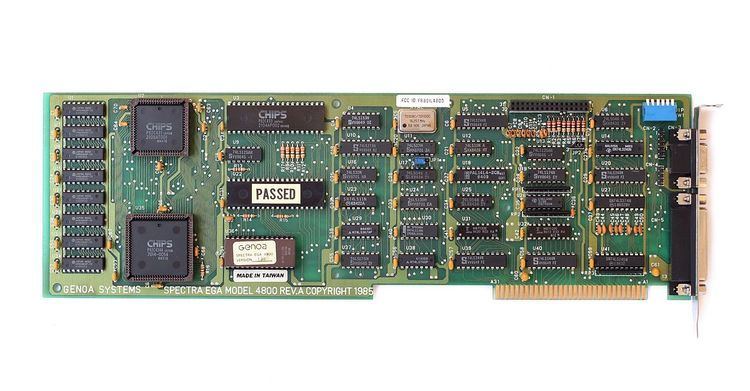
Shortly before the introduction of VGA, Genoa Systems introduced a half-size graphics card built around a proprietary chip set, which they called Super EGA (later cards supporting an extended version of the VGA were similarly named Super VGA).
Design
EGA produces a display of sixteen simultaneous colors from a palette of sixty-four, at a resolution of up to 640×350 pixels. The EGA card includes a 16 KB ROM to extend the system BIOS for additional graphics functions, and includes a custom CRT controller that has a backward compatibility mode with the Motorola MC6845 chip used to generate video timing signals in earlier graphics controllers.
In the 640×350 high resolution mode, each of the sixteen colors can be selected from a palette comprising all possible combinations of two bits per pixel each for red, green and blue, allowing four levels of intensity for each primary color and sixty-four possible colors overall. EGA also includes full sixteen-color versions of the CGA 640×200 and 320×200 graphics modes; only the sixteen CGA/RGBI colors are available in these modes. EGA four-bit (sixteen colors) graphic modes are also notable for a sophisticated use of bit planes and mask registers together with CPU bitwise operations, which constitutes an early graphics accelerator inherited by VGA and numerous compatible hardware.
EGA is dual-sync; it scans at 21.8 kHz when 350-line modes are used and 15.7 kHz when 200-line modes are used. The original CGA modes are also present, though EGA is not 100% hardware compatible with CGA. EGA can drive an MDA monitor by a special setting of switches on the board; only 640×350 high-resolution monochrome graphics and the standard MDA text mode are available in this mode.
EGA cards use the PC ISA bus and were available starting in both eight- and sixteen-bit versions. The original IBM EGA card had 64 KB of onboard RAM and required a daughter-board to add an additional 64 KB (cards with 64 KB are limited to four colors when 640×350 mode is used). All third-party cards came with 128 KB already installed and some even 256 KB, allowing multiple graphics pages. A few third-party EGA clones (notably the ATI Technologies and Paradise boards) feature a range of extended graphics modes (e.g., 640×400, 640×480 and 720×540), as well as automatic monitor type detection, and sometimes also a special 400-line interlace mode for use on CGA monitors.
Output capabilities
EGA supports:
Text modes:
Extended graphics modes of third party boards:
Color palette
The EGA palette allows all 16 CGA colors to be used simultaneously, and it allows substitution of each of these colors with any one from a total of 64 colors (two bits each for red, green and blue). This also allows the CGA's alternate brown color to be used without any additional display hardware. The later VGA standard built on this by allowing each of the 64 colors to be further customized. The extended color palette cannot be used in 200-line modes.
When selecting a color from the EGA palette, two bits are used for the red, green and blue channels. This allows each channel a value of 0, 1, 2 or 3. To select the color magenta, the red and blue values would be medium intensity (2, or 10 in binary) and the green value would be off (0). When calculating the intended value in the 64-color EGA palette, the binary number of the intended entry is of the form "rgbRGB" where a lowercase letter is the least significant bit of the channel intensity and an uppercase letter is the most significant bit. For magenta, the most significant bit in the red and blue values is a 1, so the uppercase R and B placeholders would become 1. All other digits are zeros, giving the binary number 000101 for the color magenta. This is 5 in decimal, so setting a palette entry to 5 would result in it being set to magenta. All the color values for the default colors are listed in the table on the right.
Specifications
The EGA uses a female nine-pin D-subminiature (DE-9) connector which looks identical to the CGA connector. The hardware signal interface, including the pin configuration, is largely compatible with CGA. The differences are in the re-purposing of three pins for the EGA's secondary RGB signals: the CGA "Intensity" pin (pin six) has been changed to "Secondary Green (Intensity)"; the second ground of CGA (pin two) has been changed to "Secondary Red (Intensity)", and pin seven (Reserved on the CGA) is now used for "Secondary Blue (Intensity)". If the EGA is operated in modes having the same scan rates as CGA, a connected CGA monitor should operate correctly, though if the monitor connects pin two to ground, the shorting of the EGA's secondary red output to ground could conceivably damage the EGA adapter. Similarly, if the CGA monitor is wired with pin two as its sole ground (which is poor design), it will not work with the EGA, though it will work with a CGA. Finally, because of the use of the CGA's intensity pin as secondary green, on a CGA monitor connected to an EGA, all CGA colors will display correctly, but all other EGA colors will incorrectly display as the standard CGA color which has the same values for the g, R, G, and B bits (ignoring the r and b bits.) Conversely, an EGA monitor should work with a CGA adapter, but the secondary red signal will be grounded (always zero) and the secondary blue will be floating (unconnected), causing all high-intensity CGA colors except brown to display incorrectly, and all colors to potentially have a variable blue tint due to the indeterminate state of the unconnected secondary blue.
Almost all EGA cards have DIP switches on the back of the card to select the monitor type. If CGA is selected, the card will operate in 200-line mode and use 8x8 characters in text mode. 350-line modes cannot be accessed, nor any of the extended color palette. If EGA is selected, the card will operate in 350-line mode and use 8×14 text. When 200-line modes are set, it will sync down to 15 kHz. If MDA is selected, the card also uses 350 lines and 8×14 text, but the only graphics mode that can be accessed is 640×350×2.
The IBM 5154 EGA monitor has a special IBM 5153 CGA compatibility mode when operating with CGA sync signals, and it will automatically change to the CGA pinout to avoid all of the mentioned problems when operating in this mode.
Memory mapping
EGA graphics modes are planar, as opposed to the interlaced CGA and Hercules modes. The video memory is divided into four pages (except 640×350×2, which has two pages), one for each component of the RGBI color space. Each bit represents one pixel. If a bit in the red page is enabled, but none of the equivalent bits in the other pages are, a red pixel will appear in that location on-screen. If all the other bits for that particular pixel were also enabled, it would become white, and so forth. The planes are 8 KB in size (200-line modes and 640×350 with two colors), 16 KB (640×350 with 64 KB video RAM), or 32 KB (640×350 with 128 KB video RAM) and reside at segment A000 in the CPU's address space. They are bank-switched and only one plane can be read from at once, although the programmer may set the control registers on the EGA card to select which planes are written to. Thus, it is possible to write to all of them at once even though just one plane can be read from at any given moment.
Color text and CGA modes reside in segment B800, and monochrome text at B000 for backwards compatibility.
Connector
Female DE-9 connector, on EGA (computer).
Pin numbers (looking at socket): top row is pins 1–5, bottom row is pins 6 to 9, both numbered from right to left in this illustration.
Adoption
Commercial software began supporting EGA by 1986 and Sierra's King's Quest 3 was one of the earliest games to use it. Most software made up to 1991 can run in EGA, although the vast majority of commercial games used 320×200 with 16 colors for reasons of compatibility with CGA and Tandy and to support users who did not own a proper EGA monitor. The 350-line modes were mostly used by freeware/shareware games and application software, although SimCity is a notable example of a commercial game that runs in 640×350×16 mode.