
 | ||
The Elliott 803 is a small, medium-speed digital computer which was manufactured by the British company Elliott Brothers in the 1960s. About 250 were built and most British universities and colleges bought one.
Contents
History
The 800 series started with the 801, a one-off test machine built in 1957. The 802 was a production model but only seven were sold between 1958 and 1961. The short-lived 803A was built in 1959 and first delivered in 1960; the 803B was built in 1960 and first delivered in 1961. Elliott subsequently developed the much faster Elliott 503 computer to be software compatible.
Over 200 Elliott 803 computers were delivered to customers, at a price of about £29,000 in 1960 (roughly equivalent to £602,000 in 2015). The majority of sales were the 803B version with more parallel paths internally, larger memory and hardware floating-point operations. In 2010, two complete Elliott 803 computers survive. One is owned by the Science Museum (London) but it is not on display to the public. The second one is owned by The National Museum of Computing (TNMoC) at Bletchley Park and is fully functional. Both machines are the subject of a Computer Conservation Society restoration and maintenance project which currently concentrates on the machine at TNMoC. Consequently, this machine can regularly be seen in operation by visitors to that museum. An incomplete third Elliott 803 was found decaying in a scrap yard. Where possible, parts were removed for use as a source of spares for the machine at TNMoC.
The Elliott 803 was the computer used in ISI-609 process control system. The ISI-609 was the world's first process control system; the Elliott 803's role in this system was a data logger and it was used for this purpose at the world's first dual-purpose reactor (N-Reactor).
Hardware description
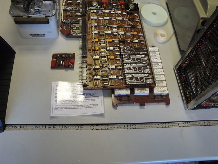
The 803 is a transistorised, bit-serial machine; the 803B has more parallel paths internally. It uses ferrite core memory in 4096 or 8192 words of 40 bits, comprising 39 bits of data with parity. The CPU is housed in a single cabinet about 66 inches long, 16 inches deep and 56 inches high. Circuitry is based on printed circuit boards with the printed circuits being rather simple and most of the signalling carried on wires. There is a second cabinet about half the size used for the power supply, which is unusually based on a large nickel-cadmium battery with charger, an early form of uninterruptible power supply. A third cabinet (the same size as the power cabinet) holds the extra working store on machines with 8192 word stores. There is an operator's control console, Creed teleprinter and high-speed paper tape reader and punch for input/output, using 5-track Elliott telecode code, not Baudot. Tape is read at 500 characters per second and punched at 100 cps. The operator's console, about 60 inches long, allows low-level instructions to be entered manually to manipulate addresses and data and can start, stop and step the machine: there is a loudspeaker (pulsed by the top bit of the instruction register) which allows the operator to judge the status of a computation. The system requires air conditioning, drawing about 3.5 kW of power in a minimal configuration.
Optional mass storage is available on an unusual magnetic tape system based on standard 35 mm film stock coated with iron oxide (manufactured by Kodak). At the time this was in use by the film industry to record sound tracks. Elliott's factory at Borehamwood was close to the Elstree film studios which explains the use of the 35mm sprocketed media. The 1000 foot reels held 4096 blocks of 64 words per block (4096 x 64 x 39 = 10,223,616 bits, or the equivalent of about 1.27Mbytes).
Another unusual feature is the use of magnetic cores not only for memory but also as logic gates. These logic cores have 1, 2 or 3 input windings, a trigger (read) and an output winding. Depending on their polarity, current pulses in the input windings either magnetise the core or cancel each other out. The magnetised state of the core indicates the result of a boolean logic function. Two clock phases designated alpha and beta are used to trigger (reset to zero) alternate cores. A change from a one to a zero produces a pulse on the output winding. Cores which receive alpha trigger pulses (alpha cores) have inputs fed from gates which are triggered on the beta phase (beta cores). Transistors were expensive at the time and each logic gate requires only one to amplify the output winding pulse; however a single transistor drives the inputs of a small number of (typically 3) other cores. If more than 3 inputs are to be driven, up to two additional transistors can be driven by each core.
Instruction set
Instructions and data are based on a 39-bit word length with binary representation in 2's complement arithmetic. The instruction set operates on a single address and single accumulator register, with an additional auxiliary register for double length integer multiply and divide. Although it is believed that the single length divide and square root instructions were only enabled in 803s destined for process control applications, the one remaining operational 803B has been found to have these instructions enabled, probably because it was used by a software house to develop real time and process control applications. An instruction is composed of a 6-bit instruction (conventionally represented in octal) and a 13 bit address. This gives 64 instructions organised as 8 groups of 8 instructions. The 13 bit memory address field gives an addressable range of 8192 words. These 19-bit instructions are packed two to a word with an additional 39th bit between them, the so-called B-line or B digit (the term is a legacy from the Ferranti Mark 1 computer, where the A-line represented the accumulator and the B-line an instruction modifier, both displayed on a Williams tube). Setting the B digit has the effect of adding the contents of the memory address of the first instruction to the second instruction at execution time, enabling indirect addressing and other run-time instruction modifications. The bit time is 6 microseconds, jumps execute in 288 microseconds and simple arithmetic instructions in 576 microseconds. Floating point operations take several milliseconds. IO is direct and there are no interrupts.
In the following descriptions, A and N represent the accumulator and the literal address, a and n represent the (initial) contents of the accumulator and addressed store location, and a' and n' the resultant contents.
Instruction Groups 0 - 3
These are fixed point arithmetic with 4 different combinations of operand and result destination:
Instruction Group 4
Group 4 is conditional and unconditional jumps. Functions 40 - 43 jump to the first instruction of a pair, and 44 - 47 to the second.
Instruction Group 5
Group 5 is multiply, divide and shift instructions. Some of these use the 38-bit Auxiliary Register (AR - contents denoted by ar), which can be thought of as an extension of the accumulator at the least significant end. Multiplications and divisions regard a/ar as a signed fraction between -1 and one least significant bit less than +1. Despite the 803 Handbook saying "All odd functions in Group 5 clear the AR", function 57 does not clear it.
Instruction Group 6
Group 6 is floating point instructions (if a floating point unit is installed).
Floating point numbers are represented in a 39 bit word or in the accumulator as (from most to least significant end):
Zero is always represented by all 39 bits zero.
Note that the test for zero and test for negative jump instructions are equally valid for floating point.
All these instructions clear the auxiliary register.
Instruction Group 7
Group 7 is input/output, with the exception of 73, which is used for subroutine linkage. There is a much more complete description of the Group 7 functions in the "Our Computer Heritage" link.
Digital Plotter Control:
Entry to a subroutine at address N is normally effected by the sequence:
73 LINK : 40 NThe return address has been stored in a link location (typically the location before the start of the subroutine (e.g. N-1) )
and returns by using the sequence:
00 LINK / 40 1Example program
By way of an example, the following is the Initial Instructions, hard-wired into locations 0 - 3, and used for loading binary code from paper tape into memory. In accordance with the 803 convention, it is written with two instructions on each line, representing the contents of one word. The colon or slash between them represent a B digit value of zero or one respectively.
0: 26 4 : 06 0 Clear loc'n 4; Clear A 1: 22 4 / 16 3 Increment loc 4; Store A in loc'n (3 + content of loc'n 4) & clear A 2: 55 5 : 71 0 Left shift A 5 times; Read tape and "or" into A 3: 43 1 : 40 2 Jump to loc'n 1 if arith overflow; Jump to loc'n 2There are several interesting and subtle points to note in this very simple program:
(In fact the data values for the wrapped-around locations 0 - 3 must be zero since counter values 8192, 8193 etc. change the B-modified second half of location 1 from a 16 to a 17 instruction, which sets a to n - a instead of clearing it, as required by the inner loop.)
Interrupts
The 803 has a little-known interrupt facility. Whilst it is not mentioned in the programming guide and is not used by any of the standard peripherals, the operation of the interrupt logic is described in the 803 hardware handbooks and the logic is shown in the 803 maintenance diagrams (Diagram 1:LB7 Gb). Interrupts are probably used mostly in conjunction with custom interfaces provided as part of ARCH real time process control systems. Since all input and output instructions causes the 803 to become "busy" if input data is not available or if an output device has not completed a previous operation, interrupts are not needed and are not used for driving the standard peripherals.
Raising the interrupt input to the computer causes a break in execution as follows: as soon as the machine is in a suitable state (in particular, when not "busy" and only in certain states of the fetch/execute cycle), the next instruction pair is fetched from store location 5, without changing the Sequence Control Register (SCR). Location 5 is expected to contain a standard subroutine entry instruction pair (73 LINK : 40 N - see above), allowing the pre-interrupt execution address (still in the SCR) to be saved for later return. The external equipment raising the interrupt is relied upon to refrain from raising another interrupt until the first has been acknowledged by some suitable input/output instruction, so as to prevent interrupts from being nested. Interestingly, the Algol compiler does not regard location 5 as a reserved location, although this may have more to do with the unsuitability of Algol for process control applications than indicating that interrupts are never regarded as a mainstream facility.
Compilers
The Initial Instructions described as the Example Program above is effectively a primary bootloader which is normally used to read a secondary bootloader known as T23, prepended to all program tapes. T23 allows more flexible program loading facilities including sumchecking of the loaded code.
Machine code programs are written in an octal/decimal representation exemplified in the Example Program above, and loaded by a rudimentary assembler known as the Translation Input Routine. It has no symbolic addressing facilities, but instead allows the source to be broken into blocks which can be manually relocated to allow for the expansion or contraction of a previous block in development. There is also an Autocode for simple programming tasks, allowing faster program development without the need for a knowledge of machine code. This has no formula translation facilities and requires all calculations to be reduced to a series of assignments with no more than a single operator on the right hand side.
The 803B with 8192 words of memory is capable of running the Elliott ALGOL compiler, a major subset of the Algol60 language, capable of loading and running several ALGOL programs in succession. This was largely written by Tony Hoare, employed by Elliotts as a programmer in August 1960. Hoare recounts some of his experiences at Elliotts in his 1980 ACM Turing Award lecture.
The 803B at The National Museum of Computing is now working well enough to run this compiler again. There is a short video on YouTube of it compiling and running a simple program.
NCR involvement
The 803 was branded as the NCR-Elliott 803 when sold by NCR for commercial use. At this time, Elliott Automation were also making/assembling NCR 315's at Borehamwood.
Do-it-yourself computing
Elliott 803's (and later Elliott 4100's) were use in NCR-Elliott's joint venture "Computer Workshop" computer bureau. The unique feature of this bureau was that they ran 3-day courses to teach their customers to write their own programmes, and these were often donated to a library of programmes that could be used. Customers would come to Borehamwood (and later Greenford) to operate the computers themselves - an early example of personal computing. Prices were £8 per hour from 9 am to 5 pm, £6 per hour from 5 pm to midnight, and £4 per hour from midnight to 9 am.
The most popular applications were civil engineering and architecture - structural analysis, cut and fill, survey correction and bills of quantities.
Applications
The following users are all listed in
A small number of second-hand 803s found their way into schools in the UK.