
 | ||
A familiar explanation of how a turbomachine produces thrust or power, and how much fuel it uses, treats the internal parts, including the compressor and turbine, as 'black boxes'. They have entry and exit flows, pressures and temperatures and they have efficiences. This article looks inside the 'black boxes' by explaining some things which determine the efficiences of the compressor and turbine. These things relate to boundary layer behaviour in the presence of local regions of supersonic flow and associated shock losses.
Contents
- Estimation of shock losses
- Formation of separation bubble and trailing edge shock structure
- Mee et al 1992
- Martelli and Boretti 1985
- References
High Mach number signifies high mass flow per unit area as well as high pressure ratios across the stage. Shock wave generation which occurs with the Mach number levels used in turbo-machines decreases the efficiency of the machine owing to entropy generation. For compressors the analysis of pressure variation across the stage uses
p2/ p1 = 1+(Cp*γ*M2/2)
where
p = Static pressure
Cp = Pressure drop or rise coefficient
γ = Specific heat of gas
M = Mach number
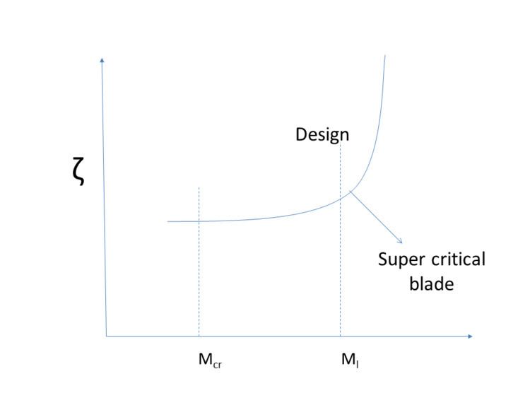
For high subsonic flows, the Critical Mach number (M1cr) is a characteristic value of considerable importance. It is the Mach number for which sonic conditions are reached locally in the flow field i.e. there will be no shocks. To minimize shock losses and profile losses, the turbo-machine should be operated below M1cr. The Mach number range can also be extended beyond M1cr by carefully designing blade shapes.
As the relative Mach number increases, so does the value of Cp, leading to an increase in static pressure in compressors, and, in turn, rises in the boundary-layer thickness and losses. So for a given incidence, off-design losses will increase with increasing Mach number and there will be a drastic increase close to a critical Mach number, resulting in shock waves inside passages.
Estimation of shock losses
For consideration of two-dimensional shock losses for a compressor, three major contributing factors have been considered:
- Bluntness of the leading edge with supersonic upstream Mach Number.
- Location and strength of passage shock.
- Losses from boundary growth and shock-boundary-layer interaction. (Very small for weak shocks)
Koch and Smith in 1976 were the first to develop a correlation for estimating the shock loss coefficient (ζsh). The models used were empirical correlations for leading-edge losses and passage shock loss models. They assumed that the passage shock loss is equivalent to the entropy rise of oblique shocks that reduce passage inlet Mach number to unity. Some results of their experiments are shown in the following figure:
Formation of separation bubble and trailing edge shock structure
The adverse pressure gradient which can be caused by the blade loading factor may result in the separation of the boundary layer. The layer may become separated at the trailing edge and re-attach depending on the flow separation, causing the formation of a separation bubble. The flow becomes fully turbulent after the reattachment and the boundary layer will separate near the trailing edge as the incident shocks strike the suction surface.
Boundary layers in turbines are thinner than in compressors, and increasing the Mach number along the suction surface up to the trailing edge makes the layer thinner. A laminar boundary layer tends to become separated due to the adverse pressure gradient, while the turbulent has less tendency to separate. However, the turbulent boundary layer will have higher viscous loss compares to the laminar one.
Shock is formed in transonic turbines at the trailing edge, when the Mach number reaches unity. When the Mach number is increased further, the normal shocks transform to oblique shocks. The shock formed on the pressure surface will impinge onto the suction surface of the blade and is reflected back as a shock. The incident shock on the suction surface will produce a pressure rise. The viscous layer near the impingement point increases its momentum and thickness to overcome the pressure rise in that region, resulting in separation of the localized boundary layer.
- Profile loss associated with boundary layer growth.
- Shock loss arising from normal or oblique shocks at trailing edge.
- Mixing loss due to rapid dissipation of the wake and shock-boundary layer interaction.
The profile loss in a transonic turbine consists of (1) the loss due to the boundary layer and wake (ζp), (2) the loss associated with the trailing edge shock system (ζsh)
In transonic flow, the trailing edge shock system and its interaction with the blade boundary layer and wake may surpass the losses due to the blade boundary layer alone. The trailing edge and mixing losses account for a large portion of the total losses. Mee et al. (1990) recorded 70-90% of the total losses associated with the trailing edge shock,wake mixing and separation bubble. In some cases,the total loss can be 100% due to the major key losses at transonic flow, exceeding mach number unity. The trailing edge losses are dependent on blade profile, including curvature, near the trailing edge and thickness.
Mee et al. (1992)
Mee et al. (1992) carried out a systematic experimental program to identify contributions to the loss from various sources in a turbine blade row. The investigations were carried out at a blow-down wind tunnel.
Cascade parameters taken are as follows:
α1= 42.8°
M1= 0.31
α2= -68.0°
M2= 0.92
Chord (C) = 230.7 mm
Span (S) = 252.1 mm
It is the evident that boundary layer profile loss dominates at subsonic exit mach numbers and the downstream wake mixing is about 30% of the total loss. But when the shock wave develops, the shock and the mixing losses dominates with nearly 100% increase in total losses at Mexit = 1.2. Part of mixing losses can be attributed to either the shock (which brings about sudden increase in the thickness of boundary layer) or the wake mixing losses. Wake width measured downstream increases rapidly with an increase in the mach number, while the wake width is nearly identical at the trailing edge.
Martelli and Boretti (1985)
They developed a method for transonic turbine cascade. For Mach number (M)>1.2 at exit conditions, a two oblique shock structure is formed at the trailing edge. Trailing edge shock is produced at the downstream of the shock due to flow acceleration. The mixing of two supersonic jets, results in a re-attachment shock.
Following calculations are to be considered to calculate the Losses:
- Pressure distribution:
- Pressure-correction method (PCM), developed by Pratap and Spalding (1976).
- Pressure substitution method (PSM), developed by Hobson and Lakshminaranaya (1991).
- Trailing edge flow: Analysis of the supersonic exit.
- Boundary layer calculations:
- Nature of boundary layers.
- Numerical solution of Boundary layer Equations.
- One-dimensional analysis is carried out in a control volume to estimate all the losses.
Maritelli and Boretti computed and compared measured losses for various types of blading.
In the case of Mee et al. (1992), the sudden increase in Mach number from 0.9-1.0 increases the losses due to shock and substantially the total loss. While in case of Maritelli and Boretti, the maximum losses occur beyond M2 = 1.0. In the later case, as the mach number (M) is increased, the shock wave emanating from one vane swings downstream and this impinges further downstream on the suction surface resulting in lower losses.