
Initial release August 2004 Written in Object Pascal (Delphi) | Stable release 3.0 / March 10, 2016 | |
 | ||
Operating system Available in available in English and 21 other languages Type Electronic design automation | ||
DipTrace is EDA/CAD software for creating schematic diagrams and printed circuit boards. The developers provide multi-lingual interface and tutorials (currently available in English and 21 other languages). DipTrace has 4 modules: Schematic Capture Editor, PCB Layout Editor with built-in shape-based autorouter and 3D Preview & Export, Component Editor, and Pattern Editor.
Contents
Schematic Capture
Advanced circuit design tool with support of multi-sheet and multi-level hierarchical schematics that delivers a number of features for visual and logical pin connections. Cross-module management ensures that principal circuits can be easily converted to PCB, back annotated, or imported/exported from/to other EDA, CAD formats and net-lists. DipTrace Schematic has ERC Verification and Spice export for external simulation.
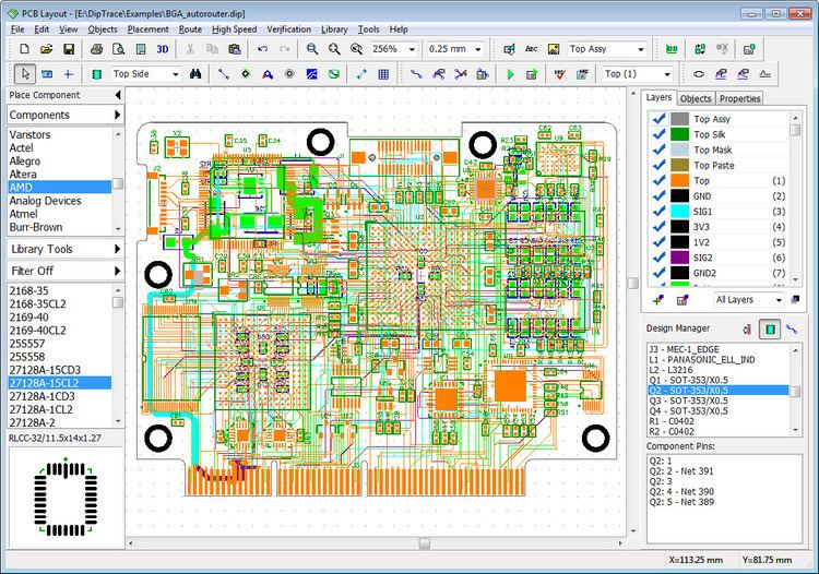
PCB Layout
Engineering tool for board design with smart manual routing, differential pairs, shape-based autorouter, advanced verification, and wide import/export capabilities. Design requirements are defined by net classes, class-to-class rules, and detailed settings by object types for each class or layer. When routing with real-time DRC, the program reports errors on the fly before actually making them. DRC also checks length and phase tolerances for differential pairs. The board can be previewed in 3D and exported to STEP format for mechanical CAD modeling. Design Rule Check with in-depth detailing and Net Connectivity verification procedures are available.
3D Preview and Export
This module includes real-time 3D preview & export feature. It shows the model of manufactured printed circuit board with all components installed. Rotate board in three axes, zoom in and out in real time, change colors of the board, copper areas, solder mask, silkscreen, and background. 3D preview works on all stages of the design. Board can be exported to STEP or VRML 2.0 formats for mechanical CAD modelling. More than 6500 3D models of PCB packages are supplied for free. Externally designed 3D models in *.wrl, *.step, *.iges, and *.3ds formats can be uploaded and attached to patterns in Pattern Editor or PCB Layout.
Component Editor
Manage component libraries and create single- or multi-part components by selecting a template and its dimensions, defining visual and electrical pin parameters, setting up a Spice model, and attaching pattern with a 3D model to finalize component creation. BSDL import, bulk pin naming, and pin manager tools for pins and buses. Importing libraries from different EDA formats. More than 130000 components in standard libraries.
Pattern Editor
Draw patterns with various types of shapes, pads, holes, and dimensions. Circle, Lines (headers, DIP), Square (QFP), Matrix (BGA), Rectangle (RQFP), and Zig-Zag standard templates. Creation of pattern is basically selecting a template, entering a couple of vital parameters, drawing the silkscreen, and launching automatic pad renumbering. Custom templates can be created for non-standard patterns. DXF import makes creating complex layouts easier.
Freeware and Hobbyist versions
A version of DipTrace is freely available with all the functionality of the full package except that it is limited to 300 pins and non-commercial use or 500 pins (non-commercial use, for a moderate charge) and 2 signal layers. Power and ground plane layers do not count as signal layers, so the free versions can create 4-layer boards with full power and ground planes.