
 | ||
A digital differential analyzer (DDA), also sometimes called a digital integrating computer, is a digital implementation of a differential analyzer. The integrators in a DDA are implemented as accumulators, with the numeric result converted back to a pulse rate by the overflow of the accumulator.
Contents
The primary advantages of a DDA over the conventional analog differential analyzer are greater precision of the results and the lack of drift/noise/slip/lash in the calculations. The precision is only limited by register size and the resulting accumulated rounding/truncation errors of repeated addition. Digital electronics inherently lacks the temperature sensitive drift and noise level issues of analog electronics and the slippage and "lash" issues of mechanical analog systems.
For problems that can be expressed as differential equations, a DDA can solve them much faster than a general purpose computer (using similar technology). However reprogramming a DDA to solve a different problem (or fix a bug) is much harder than reprogramming a general purpose computer. Many DDAs were hardwired for one problem only and could not be reprogrammed without redesigning them.
History
One of the inspirations for ENIAC was the mechanical analog Bush differential analyzer. It influenced both the architecture and programming method chosen. However, although ENIAC as originally configured, could have been programmed as a DDA (the "numerical integrator" in Electronic Numerical Integrator And Computer), there is no evidence that it ever actually was. The theory of DDAs was not developed until 1949, one year after ENIAC had been reconfigured as a stored program computer.
The first DDA built was the Magnetic Drum Digital Differential Analyzer of 1950.
Theory
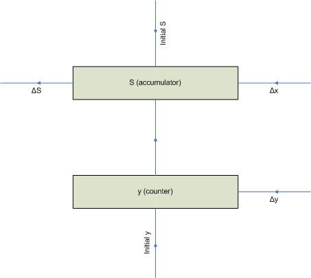
The basic DDA integrator, shown in the figure, implements numerical rectangular integration via the following equations:
Where Δx causes y to be added to (or subtracted from) S, Δy causes y to be incremented (or decremented), and ΔS is caused by an overflow (or underflow) of the S accumulator. Both registers and the three Δ signals are signed values. Initial conditions for the problem can be loaded into both y and S prior to beginning integration.
This produces an integrator approximating the following equation:
where K is a scaling constant determined by the precision (size) of the registers as follows:
where radix is the numeric base used (typically 2) in the registers and n is the number of places in the registers.
If Δy is eliminated, making y a constant, then the DDA integrator reduces to a device called a rate multiplier, where the pulse rate ΔS is proportional to the product of y and Δx by the following equation: