
 | ||
A dielectric resonator is a piece of dielectric (nonconductive) material, usually ceramic, that is designed to function as a resonator for radio waves, generally in the microwave and millimeter wave bands. The microwaves are confined inside the resonator material by the abrupt change in permittivity at the surface, and bounce back and forth between the sides. At certain frequencies, the resonant frequencies, the microwaves form standing waves in the resonator, oscillating with large amplitudes. Dielectric resonators generally consist of a "puck" of ceramic that has a large dielectric constant and a low dissipation factor. The resonant frequency is determined by the overall physical dimensions of the resonator and the dielectric constant of the material.
Contents
Dielectric resonators function similarly to cavity resonators, hollow metal boxes that are also widely used as resonators at microwave frequencies, except that the radio waves are reflected by the large change in permittivity rather than by the conductivity of metal. At millimeter wave frequencies, metal surfaces become lossy reflectors, so dielectric resonators are used at these frequencies. Dielectric resonators' main use is in millimeter-wave electronic oscillators (dielectric resonator oscillator, DRO) to control the frequency of the radio waves generated. They are also used as bandpass filters as well as antennas.
Historical overview
In the late 19th century, Lord Rayleigh demonstrated that an infinitely long cylindrical rod made up of dielectric material could serve as a waveguide. Additional theoretical and experimental work done in Germany in early 20th century, offered further insight into the behavior of electromagnetic waves in dielectic rod waveguides. Since a dielectric resonator can be thought of as a truncated dielectric rod waveguide, this research was essential for scientific understanding of electromagnetic phenomena in dielectric resonators. In 1939 Robert D. Richtmyer published a study in which he showed that dielectric structures can act just as metallic cavity resonators. He appropriately named these structures dielectric resonators. Richtmyer also demonstrated that, if exposed to free space, dielectic resonators must radiate because of the boundary conditions at the dielectric-to-air interface. These results were later used in development of DRA (Dielectric Resonator Antenna). Due to World War II, lack of advanced materials and adequate manufacturing techniques, dielectric resonators fell in relative obscurity for another two decades after Richtmyer's study was published. However, in the 1960s, as high-frequency electronics and modern communications industry started to take off, dielectric resonators gained in significance. They offered a size-reducing design alternative to bulky waveguide filters and lower-cost alternatives for electronic oscillator, frequency selective limiter and slow-wave circuits. In addition to cost and size, other advantages that dielectric resonators have over conventional metal cavity resonators are lower weight, material availability, and ease of manufacturing. There is a vast availability of different dielectric resonators on the market today with unloaded Q factor on the order of 10000s.
Theory of operation
Although dielectric resonators display many similarities to resonant metal cavities, there is one important difference between the two: while the electric and magnetic fields are zero outside the walls of the metal cavity (i.e. open circuit boundary conditions are fully satisfied), these fields are not zero outside the dielectric walls of the resonator (i.e. open circuit boundary conditions are approximately satisfied). Even so, electric and magnetic fields decay from their maximum values considerably when they are away from the resonator walls. Most of the energy is stored in the resonator at a given resonant frequency for a sufficiently high dielectric constant
There are three types of resonant modes that can be excited in dielectric resonators: transverse electric (TE), transverse magnetic (TM) or hybrid electromagnetic (HEM) modes. Theoretically, there is an infinite number of modes in each of the three groups, and desired mode is usually selected based on the application requirements. Generally,
Approximate resonant frequency of
Where
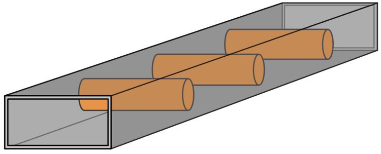
However, since a dielectric resonator is usually enclosed in a conducting cavity for most applications, the real resonant frequencies are different from the one calculated above. As conducting walls of the enclosing cavity approach the resonator, change in boundary conditions and field containment start to affect resonant frequencies. The size and type of the material encapsulating the cavity can drastically impact the performance of the resonant circuit. This phenomenon can be explained using cavity perturbation theory. If a resonator is enclosed in a metallic cavity, resonant frequencies change in following fashion:
The most common problem exhibited by dielectric resonator circuits is their sensitivity to temperature variation and mechanical vibrations. Even though recent improvements in materials science and manufacturing mitigated some of these issues, compensating techniques still may be required to stabilize the circuit performance over temperature and frequency.
Common applications
The most common applications, of dielectric resonators are: