
Status Operational | Purpose Power Construction began October 2009 (2009-10) | |
 | ||
Opening date February 2012 (2012-02) Similar Sinharaja Forest Reserve, Udawalawe National Park, Maha Saman Devalaya, Pinnawala Elephant Orphanage, Ridiyagama Safari Park | ||
Denawaka Ganga Mini Hydro Power Project is a run of river mini hydro power project located in Ratnapura, Sri Lanka.The install capacity of the project is 7.2MW and the annual generation is 25GWh. The generated energy is fed into the national electric grid of Sri Lanka.
Contents
Location
Topography surveys of the project area are available in the sheet 75 – Balangoda which in the scale of 1:50,000 by Survey Department of Sri Lanka. The Geo Coordinates of the project activity as follows, Weir - 06° 41’ 39” N & 80° 28’ 06” E Power Plant - 06° 42’ 12” N & 80° 26’ 59” E
The project location is close to the town of Ratnapura approximately 115 km from Colombo, and the project is accessible from the main Ratnapura-Balangoda road. The site is reached by turning right just beyond the Malwala town and proceeding approximately 3 km on a by-road.
Project Implementation
The project developer is Country Energy (Pvt) Ltd, a subsidiary of Vallibel Power Erathna PLC which is one of the leading mini hydro power developers in Sri Lanka,.
The development of the project was initiated in September 2002 with the investigation of the feasibility of the project and it was decided to develop the project with a capacity of 4.9MW. It took few years to go through various regulatory clearances from the government authorities and a portion of government land was released in year 2008 after a long process. Vallibel Power Erathna PLC acquired the project in early 2009 and decided to increase the capacity up to 7.2MW after a fresh feasibility study by the Vallibel project team. Then, the construction works were started in October 2009.
The project was commenced with construction work of access road. Parallel to that, bungalow, batching plant, crusher, bulk material store yards, stores, working yards, site office and labour camps were properly structured and everything was managed in a good professional manner. This made the work more efficient and effective.
Weir
The weir of 30 m length with a maximum height of 2.5 m was constructed to divert water to the intake. The weir is a straight concrete gravity structure made of plum concrete with an ogee profile. In order to prevent silt and trash entering the channel, a trash screen was utilized.
In hydro-electric projects, a weir (dam) across the river is an important component because it builds up head and thus potential for the river water. The diversion weirs are constructed not only to raise the water level but also to divert the river flow in another direction.
Intake
Intake was constructed with 4 sluice gates of 3m width and 2.5 m height. It satisfies the requirement of getting 25m3/s flow with 1.25 m/s intake flow velocity. The intake conveys the water into the concrete headrace channel. The intake is 30m long, 20m wide and 2.2m deep,.
The intake structure is situated at the entrance of the channel which conveyed the water to the forebay. It controls the flow of water into the channel by a gate or a valve. Intake makes smooth and turbulence free water into the channel and it stops river-borne trash matter entering into the channel.
Headrace Channel
The intake leads to the rectangular profiled headrace channel of 1,800 m length which was made of reinforced concrete. The headrace channel lies on the right bank of the stream and it has 4.4m inner width and 2.2m of wall height while the design flow is 27m3/s. This bank has moderately steep slopes, and the bedrock is marginally weathered. Reinforced concrete channel sections were placed on screed concrete and expansion joints were provided at every 17m with 250mm wide rubber water bars,.
The channel is the conveyance system which water flows through from the intake to the forebay. When the general topography of the terrain is moderate with gentle slopes, channel is the appropriate conveyance system than tunnel or pipes.
Sedimentation Tank
To remove the small particles which are carried in the water, the flow must be slowed down in sedimentation tank so that the silt particles settle on the tank floor. The deposit formed should be periodically flushed away.
Spillways
Spillways are designed to control overflow at certain points along the channel and the spillways discharge the flood flow to the downstream.
Forebay
The headrace channel ends at the forebay tank. The forebay was made of reinforced concrete with a trash screen of 8.5m x 5.5m and it was placed before the penstock entry. The top of the forebay was covered while a spillway is constructed just upstream of the forebay. The forebay tank is 50m long and 9.3m wide. The maximum height of the tank is 10m,. The water carried by the channel is distributed to penstocks through the forebay tank. The water temporarily stored in the forebay in the event of a rejection of load by the turbine and there is a withdrawal from it when the load is increased. Thus the forebay acts as a sort of regulating reservoir.
Penstock
After the forebay, water divert into the penstock to deliver water into the turbines. The penstock comprises three welded steel pipes at forebay, having diameter of 1850mm each. Then the three pipes reduce to 1785mm diameter at the Anchor 2. At the third anchor, the middle pipe bifurcates into two pipes having diameters of 1220mm each and other two reduce to 1720mm diameter and continue same up to the power house. The penstock trace is geologically well stable, and minor excavation was required to construct the penstock.
The pipe was spiral welded steel made to American Petroleum Institute standards (API 5L Grade B). The pipe was brought to site in 5.8m sections and welded together at site. Total length of the steel pipes was covered with reinforced concrete and it was buried with soil. The length of the penstock is 107m and the design flow of one pipe is 8.3m2/s each of 3 pipes,.
Penstocks are the pipes that supply water from the forebay to the turbines. Penstocks are the pressure conduits and when the distance between the forebay and the power house is short, a separate penstock for each turbine is preferable.
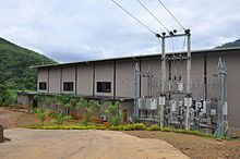
Powerhouse
The powerhouse consists of the turbines, generators and control room. The turbine bay contains a 25MT capacity crane for handling of the equipment during installation and repairs. The necessary transformer and high voltage switchgear were housed outside the powerhouse.
The project generates electricity at 6.6kV and then steps it up to 33kV via four transformers. The electricity generated exported via a 33kV transmission line of 10.2 km length to the 33kV line at the Ratnapura Grid Substation.
The powerhouse was built adjacent to the river at the downstream end of the drop. It is 54m long, 14.5m wide and 18m high.
Electro-Mechanical Equipment
The power generation units are manufactured by Dong Feng Electric Machinery Works Co., Ltd (China) and have a total capacity of 7.2 MW. More details on the applied technology as follows,
Generator 3 & 4
The hydraulic turbines coupled with the generators achieve the main objective of converting water energy to electric power. Other than the turbines and generators, a hydro power plant has various mechanical and electrical equipment such as exciters, voltage regulators, transformers and control room equipment etc.
Tailrace
The tailrace channel conveys the tail water back to the river. Tail race is the path which let the water out of the hydro power plant after power generation.
Transmission Line
The 33kV transmission line was 10.2 km long, and connected up to the 33kV line at the Ratnapura Grid Substation. A single circuit concrete pole line was built along the road from the powerhouse to the feeder. The transmission system delivers bulk power from the power station to the load centers. The electricity is transmitted by either underground cables or overhead lines.
Financial background
Total investment of the company was 905 MN LKR and Equity to debt ratio is 30:70. Debt facilities were arranged by Commercial Bank, Hatton National Bank & DFCC Bank.
Design
Power House Structural design was carried out by Stems Consultants (Pte) Ltd, while its architectural design concept from Vallibel team. The structural designer of weir, intake, channel and forebay was Mr. D.F.M. Perera. The hydraulic designs for weir, intake, channel, forebay and penstock were done by Mr. G.G. Jayawardhana, and Mr. Aruna Dheerasinghe and power house hydraulic designers were Dong Feng Electric Machinery Works Co., Ltd (China), Mr. Aruna Dheerasinghe and Mr. Sampath Abeysinghe.
The plant is commissioned on February 2012 and since then it serves Sri Lankan national grid by providing 25GWh of green energy in every year,
Environment Benefits
The renewable electricity generated by the project displaces electricity produced by fossil fuel power plants leading to lower overall emissions of SOx and NOx from the grid as a whole. In the hydro power generation process there are no greenhouse gas emissions and it does not involve burning of fossil fuels during the process. Thus, electricity generated through sustainable means without causing any negative impact on the environment. The project reduces approximately 13,500 tCO2e of annually as a result of displacement of fossil-fuel based grid electricity in Sri Lanka.
Social Development
The project activity created a lot of social benefits. It increased employment opportunities and the income of local people during the construction period. During the operation and construction period, the project created new training opportunities for the local community members. In addition, the local community was benefited with new access roads, donations to the local schools, and provision of medicines for children. In addition, the general public at large including the local residents and communities were indirectly benefited by greater availability of clean electricity in the national grid which would otherwise being met through grid connected fossil fuel based power plants.
Social Welfare
This project worked closely with the community to upgrade their standard of living and made a genuine contribution to their lives. During the construction of plant, the welfare of the community, minimal disturbance to lifestyles, construction and maintenance of the roads are prioritized. The welfare activities are as follows
Environmental Impacts
This project results in a reduction in the water flow between the weir and the powerhouse and mandatory discharge is released throughout the project life to avoid any impact on river ecosystem. The water quality does not change due to implementation of the project and there is no change in the water availability downstream too. The potential environmental impacts identified were soil erosion, loss of soil stability and slope failure, reduction in the river flow between the weir and tailrace, some ecological impacts such as interference to fish mobility, destruction of plants and noise. But, the potential impacts in this project were negligible comparatively and all the precautions were taken to minimize the impacts as on the recommendations of relevant authorities and consultants.
Achievements
Confirming that the Denawaka Ganga MHP is an environmental friendly project, UNFCCC (United Nations Framework Convention on Climate Change) registered it as a Clean Development Mechanism (CDM) project,.
CDM project consultant was Mitsubishi UFJ Morgan Stanley Securities Co., Ltd and coordination work from Country Energy (Pvt) Ltd was done under the guidance of Chief Executive Officer; Mr. Aruna Dheerasinghe by Engineer; Ms. Tharanga Baduge. The validator of the project was TÜV NORD CERT GmbH.