
 | ||
A delta modulation (DM or Δ-modulation) is an analog-to-digital and digital-to-analog signal conversion technique used for transmission of voice information where quality is not of primary importance. DM is the simplest form of differential pulse-code modulation (DPCM) where the difference between successive samples are encoded into n-bit data streams. In delta modulation, the transmitted data are reduced to a 1-bit data stream. Its main features are:
Contents
- Principle
- Transfer characteristics
- Output signal power
- Bit rate
- Adaptive delta modulation
- Applications
- SBS Application 24 kbps delta modulation
- References
To achieve high signal-to-noise ratio, delta modulation must use oversampling techniques, that is, the analog signal is sampled at a rate several times higher than the Nyquist rate.
Derived forms of delta modulation are continuously variable slope delta modulation, delta-sigma modulation, and differential modulation. Differential pulse-code modulation is the superset of DM.
Principle
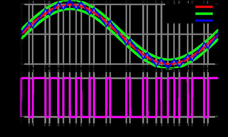
Rather than quantizing the absolute value of the input analog waveform, delta modulation quantizes the difference between the current and the previous step, as shown in the block diagram in Fig. 1.
The modulator is made by a quantizer which converts the difference between the input signal and the average of the previous steps. In its simplest form, the quantizer can be realized with a comparator referenced to 0 (two levels quantizer), whose output is 1 or 0 if the input signal is positive or negative. It is also a bit-quantizer as it quantizes only a bit at a time. The demodulator is simply an integrator (like the one in the feedback loop) whose output rises or falls with each 1 or 0 received. The integrator itself constitutes a low-pass filter.
Transfer characteristics
The transfer characteristics of a delta modulated system follows a signum function, as it quantizes only two levels and also one-bit at a time.
The two sources of noise in delta modulation are "slope overload", when step size is too small to track the original waveform, and "granularity", when step size is too large. But a 1971 study shows that slope overload is less objectionable compared to granularity than one might expect based solely on SNR measures.
Output signal power
In delta modulation there is a restriction on the amplitude of the input signal, because if the transmitted signal has a large derivative (abrupt changes) then the modulated signal can not follow the input signal and slope overload occurs. E.g. if the input signal is
the modulated signal (derivative of the input signal) which is transmitted by the modulator is
whereas the condition to avoid slope overload is
So the maximum amplitude of the input signal can be
where fs is the sampling frequency and ω is the frequency of the input signal and σ is step size in quantization. So Amax is the maximum amplitude that DM can transmit without causing the slope overload and the power of transmitted signal depends on the maximum amplitude.
Bit-rate
If the communication channel is of limited bandwidth, there is the possibility of interference in either DM or PCM. Hence, 'DM' and 'PCM' operate at same bit-rate which is equal to N times the sampling frequency.
Adaptive delta modulation
Adaptive delta modulation (ADM) was first published by Dr. John E. Abate (AT&T Bell Laboratories Fellow) in his doctoral thesis at NJ Institute Of Technology in 1968. ADM was later selected as the standard for all NASA communications between mission control and space-craft.
Adaptive delta modulation or [continuously (CVSD) is a modification of DM in which the step size is not fixed. Rather, when several consecutive bits have the same direction value, the encoder and decoder assume that slope overload is occurring, and the step size becomes progressively larger.
Otherwise, the step size becomes gradually smaller over time. ADM reduces slope error, at the expense of increasing quantizing error.This error can be reduced by using a low-pass filter. ADM provides robust performance in the presence of bit errors meaning error detection and correction are not typically used in an ADM radio design, this allows fortive-delta-modulation/</ref>
Applications
Contemporary applications of Delta Modulation includes, but is not limited to, recreating legacy synthesizer waveforms. With the increasing availability of FPGAs and game-related ASICs, sample rates are easily controlled so as to avoid slope overload and granularity issues. For example, the C64DTV used a 32 MHz sample rate, providing ample dynamic range to recreate the SID output to acceptable levels.
SBS Application 24 kbps delta modulation
Delta Modulation was used by Satellite Business Systems or SBS for its voice ports to provide long distance phone service to large domestic corporations with a significant inter-corporation communications need (such as IBM). This system was in service throughout the 1980s. The voice ports used digitally implemented 24 kbit/s delta modulation with Voice Activity Compression (VAC) and echo suppressors to control the half second echo path through the satellite. They performed formal listening tests to verify the 24 kbit/s delta modulator achieved full voice quality with no discernible degradation as compared to a high quality phone line or the standard 64 kbit/s µ-law companded PCM. This provided an eight to three improvement in satellite channel capacity. IBM developed the Satellite Communications Controller and the voice port functions.
The original proposal in 1974, used a state-of-the-art 24 kbit/s delta modulator with a single integrator and a Shindler Compander modified for gain error recovery. This proved to have less than full phone line speech quality. In 1977, one engineer with two assistants in the IBM Research Triangle Park, NC laboratory was assigned to improve the quality.
The final implementation replaced the integrator with a Predictor implemented with a two pole complex pair low-pass filter designed to approximate the long term average speech spectrum. The theory was that ideally the integrator should be a predictor designed to match the signal spectrum. A nearly perfect Shindler Compander replaced the modified version. It was found the modified compander resulted in a less than perfect step size at most signal levels and the fast gain error recovery increased the noise as determined by actual listening tests as compared to simple signal to noise measurements. The final compander achieved a very mild gain error recovery due to the natural truncation rounding error caused by twelve bit arithmetic.
The complete function of delta modulation, VAC and Echo Control for six ports was implemented in a single digital integrated circuit chip with twelve bit arithmetic. A single digital-to-analog converter (DAC) was shared by all six ports providing voltage compare functions for the modulators and feeding sample and hold circuits for the demodulator outputs. A single card held the chip, DAC and all the analog circuits for the phone line interface including transformers.