
 | ||
Deep hole drilling (DHD) is a residual stress measurement technique used to measure locked-in and applied stresses in engineering materials and components. DHD is a semi-destructive mechanical strain relaxation (MSR) technique, which seeks to measure the distribution of stresses along the axis of a drilled reference hole. The process is unique in its ability to measure residual stresses at a microscopic level with a penetration of over 750 millimetres (30 in), without total destruction of the original component. DHD is considered deep in comparison to other hole drilling techniques such as centre hole drilling.
Contents
Technique overview
DHD involves drilling a hole through the thickness of the component, measuring the diameter of the hole, trepanning (cutting a circular slot around the hole) a core of material from around the hole and finally re-measuring the diameter of the hole. For engineering metals, the trepanning process is typically performed using electrical discharge machining (EDM) to minimise the introduction of further stresses during the cutting. The differences between the measured diameters before and after stress release enables the original residual stresses to be calculated using elasticity theory. An animated YouTube video explaining the DHD technique can be viewed here: YouTube: Deep Hole Drilling Technique.
DHD procedure
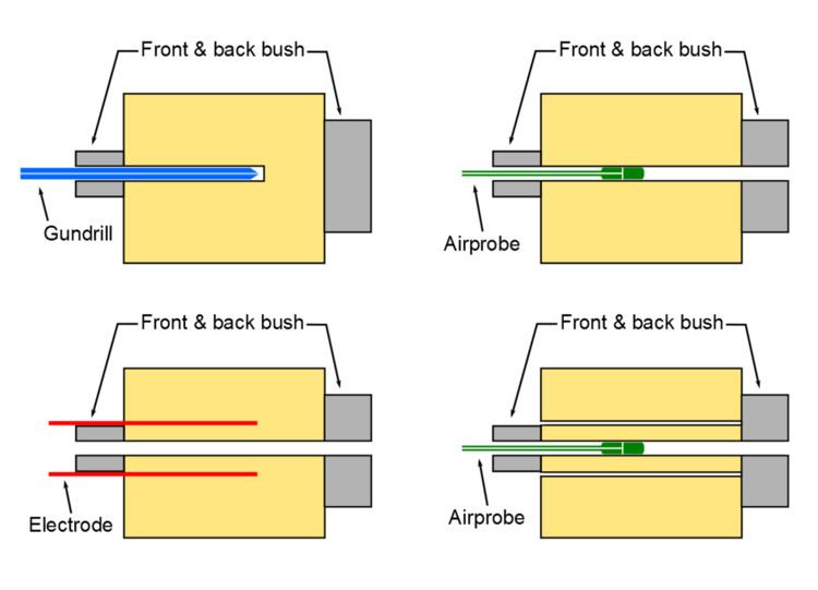
Firstly, reference bushes are attached to the front and back surfaces of the component at the measurement location, to minimise "bell-mouthing" and assist with aligning the data sets during analysis. A reference hole is then drilled through a component; in engineering metals, a gun-drill is typically used due to the smooth and straight hole profile they produce. After drilling, the diameter of the reference hole is measured at frequent intervals along the full length and circumference of the measurement and reference bushes with an air probe. This is a thin rod with pressurised air forced from the end via two small holes at a normal to the reference hole axis. As the air probe is moved through the hole, changes in hole diameter will result in changes in pressure, which are detected with a calibrated transducer to convert the pressure change into a voltage. A cylinder (i.e. a core) of material containing the reference hole along its axis is then cut (trepanned) from the component using electro-discharge machining (EDM), in order to relax the stresses acting on the reference hole. Finally, the diameter of the reference hole is re-measured through the entire thickness of the cylinder and reference bushes, with the diameter measurements taken at the same locations as those measured prior to the trepanning.
Incremental DHD technique (iDHD)
If high magnitude residual stresses (>60% yield stress) are present in the component then the DHD technique can be modified to account for plastic behaviour during the stress relief process. The risk of plastic deformation during stress relaxation is a problem in hole drilling techniques due to the approximately x3 stress concentrating factor of holes, effectively "amplifying" the stress relaxation and increasing the chance of yielding. Therefore, for iDHD, the procedure is changed to be performed incrementally, with the core being cut (trepanned) in several steps of increasing depth and the diameter measurements being performed in between each step. The analysis then incorporates this sequence of incremental distortions for calculating the high magnitude residual stresses.
Interpretation of the results
The DHD method seeks to measure the distribution of stresses along the axis of the reference hole. The relationship between the original residual stresses acting on the reference hole and the measured changes in the hole diameter creates the basis of the analysis. The DHD technique uses an elastic analysis to convert the measured distortions of the reference hole into a residual stress profile. The accuracy of the results is dependent on sources of error in the measurement, but is also dependent on the elastic modulus of the material. A lower elastic modulus will result in larger distortions for a given stress release, meaning a higher measurement resolution and thus a greater achievable accuracy. The DHD technique has a nominal accuracy of ±10MPa for Aluminium, ±30MPa for Steel and ±15MPa for Titanium.
Appraisal of the DHD technique
Advantages and disadvantages of DHD, relative to other residual stress measurement techniques, are listed below.
Advantages
Disadvantages
Validation
Several studies have been conducted to validate the DHD technique using samples with "known" stress states, by applying a defined load in the plastic range to create an internal stress state in a component, or by loading the component in the elastic range throughout the duration of the measurements.
For example, a beam component was plastically bent to introduce a known residual stress profile. These residual stresses were then measured using multiple residual stress measurement techniques including Neutron Diffraction, Slitting, Ring Core, Incremental Centre Hole Drilling, Deep Hole Drilling and Incremental Deep Hole Drilling, as well as modelled with finite element software to provide further numerical validation. The correlation between the results from techniques is strong, with DHD and iDHD displaying the same trend and magnitudes as both the numerical simulation and the other experimental techniques. The results from this comparison are shown in the Figure.