
 | ||
DCVG stands for Direct Current Voltage Gradient and is a survey technique used for assessing the effectiveness of corrosion protection on buried steel structures. In particular, oil and natural gas pipelines are routinely monitored using this technique to help locate coating faults and highlight deficiencies in their cathodic protection (CP) strategies.
Contents
History
The DCVG method was invented by Australian John Mulvany, an ex Telecom engineer, in the early 1980s. This technique was used by Telecom Australia to identify damaged insulation on buried metallic cable. At that time Santos in Adelaide was keen to utilise coating defect techniques for buried pipelines suffering corrosion in the Moomba area. Dr John Leeds, a professional corrosion engineer, was employed by Santos to engage companies with relevant expertise. Initially international companies utilising the "CIPS" and "Pearson" technique were engaged.
Ike Solomon and Matthew Wong of Wilson Walton International engaged John Mulvaney to modify the DCVG technique to make it applicable for buried pipelines. Field testing of the method was first performed on the Shell White Oil Pipeline. Subsequently, trials were performed for both Santos and The Pipeline Authority of South Australia. Vastly superior results were obtained over the other techniques. Ike Solomon and Bob Phang of Solomon Corrosion Consulting Services first demonstrated the technique overseas in the USA and Canada in 1985.
Today, the DCVG technique is universally accepted throughout the pipeline industry and is described in NACE International test method TM-0109-2009. Industry codes referring to pipe/pipeline inspection (such as API 571 and API RP 574, published by the American Petroleum Institute) reference it as a suitable method for determining coating breakdown in buried pipelines.
Background
Buried steel structures will eventually corrode if not provided corrosion control and the rate of corrosion can be unacceptably rapid in some soils or where exposed to salt water. The primary form of corrosion protection is usually one or more protective coatings, such as epoxy, bitumen, resin etc. For buried pipelines (for example), coatings alone are insufficient as corrosion will likely occur at defects and corrosion control is commonly supplemented by cathodic protection. As pipelines age coatings deteriorate and the cathodic protection becomes increasingly important in mitigating corrosion damage. Prior to the use of DCVG, assessing the condition of the pipeline coating(s) was performed using indirect techniques like close interval potential surveys or expensive excavations of the pipeline.. The DCVG technique was developed to locate coating faults, quantify their severity and measure the effectiveness of the Cathodic protection used without having to disturb the pipeline.
Principle
Assuming that the buried pipeline is protected using Impressed Current Cathodic Protection (ICCP - as are most pipelines with hazardous contents), then any defects in the coating will result in electric current flowing from the surrounding soil and into the pipe. These currents cause voltage gradients to be set up in the soil, which can be measured using a voltmeter. By looking at the direction of these gradients, the location of coating faults may be identified. By plotting the direction of voltage gradients around a fault, the type and nature of faults may be deduced. By measuring the localised soil potentials with respect to remote earth, a measure of the effectiveness of the cathodic protection may be calculated.
Practical Methods
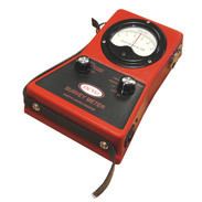
In theory, a standard analogue electronic multimeter could be used to perform a DCVG survey, but in practice it would be very difficult to take accurate readings and assess the direction of the voltage gradients correctly. A digital multimeter is completely unsuitable because of the difficulty in quickly assessing the direction of the voltage gradient. Specially designed DCVG meters are available, which have bespoke voltage ranges, specially designed transient response, rugged cases and (usually) a centre-zero meter movement for ease of use. The NACE method requires the measurements to be made using a pair of copper-copper(II) sulfate electrodes rather than simple metallic probes. In addition, the cathodic protection is switched on and off repeatedly using an electronic switch commonly referred to as an interrupter. Thus, two voltage readings (the "on" and "off" potentials) are taken at each fault position. Counter-intuitively, it is actually the "off" potential which is regarded as more indicative of the effectiveness of the CP applied to the pipeline.
Pipelines which do not have any form of CP may be surveyed by using a temporary DC supply and anode bed. Long pipelines frequently have more than one DC supply for their CP, requiring a number of synchronised interrupters to perform a survey. DCVG surveys are often combined with other techniques, such as close interval potential survey and soil resistivity as part of a comprehensive corrosion protection program.
Results of a DCVG survey often result in selecting locations to excavate pipelines, which can be costly in urban areas. Collection of data and interpretation may be performed by pipeline companies themselves or, more usually, by independent specialists.