
 | ||
DC-BUS is technology for reliable and economical communication over noisy DC or AC Power lines. The DC-BUS was originally developed by Yamar Electronics Ltd. together with the DC-BUS Alliance, for low cost sub-networks in vehicles, using the battery lines for in-vehicle data communication. The DC-BUS converts the digital input data into phase modulated signals, protected against errors generated by noise over the powerline. On the receiving side, the received signal is demodulated into the original digital data. Gradually it become a popular means of communication in a plurality of applications within Aerospace, Automotive, solar energy management and lighting. It is also used as an alternative to RS-232 and RS-485 networks in some cases. The common goal for all these applications is reducing wires, saving space, lowering cost and increasing reliability.
Contents
Technology
The DC-BUS is a physical layer that allows transmission of data over the powerline and receiving that signal even if attenuated to the noise level of the powerline. Two technologies implement the DC-BUS: Byte oriented and Message oriented. The Signaling technology is byte oriented, allowing transfer of a single UART data byte or more over noisy channel (such as the powerline) at bit-rate up to 115.2 kbit/s; Each transmitted byte is protected against errors caused by noisy environment. This method operates on a customer selected channel ranging in the HF band. A unique narrow band signaling modulation, based on combination of phase changes is used to transfer each byte. There is no restriction to the number of bytes, therefore, any UART-based standards such as RS-232, RS-485 and LIN-bus can use the DC-BUS as a physical layer. The received data by all the other nodes on that channel has a fixed latency of 3.5 bits. This simplicity of use allows every customer to design his own protocol or use common industry protocols such as LIN. A master slave upper layer protocol is suitable for network operation.
The DCB technology is message oriented, currently operating at speeds up to 1.3Mbit/s. The DCB devices use a selectable narrowband carrier to communicate over the powerline. The DCB gets a message of any length from its host controller and phase modulate it over the power line. The DCB devices have built-in CSMA/CR mechanism for collision detection and arbitration for network operation. The DCB interfaces with its host controller using Standard UART or SPI protocols. The use of low level modulated sine wave instead of digital square wave usually between 0 and 12V generates lower unintentional radiation (EMC). The DC-BUS has a Sleep mechanism to wake up the DC-BUS devices during Sleep mode (low power consumption).
Automotive
Wiring plays a significant role in automotive, a passenger car has between 500 and 1500 wires, and these numbers are growing despite the extensive use of CAN and LIN buses. Powerline is common to all the electric modules in a vehicle. The DC-BUS uses these power lines for communication. There are many applications some of them are described hereby.
Truck-trailer communication
As part of the SPARC European project conducted by Daimler, two DC-BUS communication networks were used between the truck and the trailer over the existing DC powerline. One network operated at a carrier frequency of 5 MHz for CAN redundant high speed data. The other network operated at 6.5 MHz for trailer backlights activation and control. It saved the existing lights cable between the truck and the trailer. The figure below describes the two networks saving the need for the expensive cable between the truck and the trailer. The experimental InnoTruck used the DC-BUS for its lights control.
Doors and mirrors control
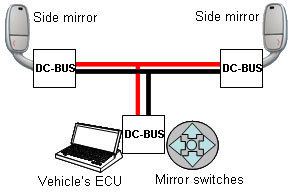
The DC-BUS can save all the wiring in doors assemblies and its mirrors by using the powerline to control the window, lock and mirror functions (up, Down, Left, Right, Blinker, etc.). Only the powerline connects the door to the vehicle body, saving connector and wires. The use of the powerline allows controlling the entertainment unit from the doors, saving the dashboard space.
Steering-wheel control
The figure below presents a steering wheel with a SIG61 device gathering all its switches status and transferring the data over the powerline to the vehicle ECU via the clock-spring saving many wires, reducing the clock spring complexity and cost.
Electrical vehicle battery management
Electrical Vehicle (EV) high voltage Battery is constructed from serially connected battery power-packs consisting of rechargeable battery cells such as Lithium-Ion. Each cell has to be monitored for proper operation within specified temperature and voltage range. Each power-pack gathers its cell's status and transfers it to the vehicle’s battery management system (BMS). Each power-pack is connected at a different voltage reference level. In traditional solution, in order to transfer data, the EV power-packs are connected to the BMS via high voltage data lines, connectors and voltage level shifters. The use of DC-BUS eliminates the need for extra wires, using the powerline as a micro-grid between the power-packs and the BMS. The Powerline communication is coupled to the BMS via capacitors that provide galvanic separation between the high voltage Powerline and the vehicle's 12/24 V Powerline.
Solar panels energy management
Photovoltaic system is constructed from arrays of solar panels and a central energy controller. Communicating between the panels and the central energy management controller allows optimization of each solar panel operating point to increase the entire system energy efficiency and to monitor its proper operation. The DC-BUS constructs a Micro-grid over the DC powerline without a need of extra wires. Strings of solar PV panels form entire data network over the high voltage powerline.
Aerospace
Saving wires in aerospace applications is obvious. The DC-BUS was used in the European SCARLETT project for harness reduction purposes.
Home appliances
Harness of white goods products can be reduced significantly by use of AC/DC-BUS between its modules. The new architecture use only two 24 V DC wires and two 110/220 V AC wires connecting all modules within the white goods products. Yamar’s semiconductors use these lines for data communication over noisy power lines; activating loads and reading sensors without need for extra wires.
The 24 V line carries the power required to operate the internal modules as well as for communication between these modules. The 110/220 V wires operate the heavy loads such as compressors and motors. Figure 1 describes a common system that is applicable in Washing machines, Air conditioners and more.
Lighting - smart home
The new generation of illumination devices (LED, CFL bulbs) contains already electronic circuitry. The DC-BUS powerline communication within these bulbs upgrades its functionality as "smart-bulb". Smart-bulb becomes an intelligent sensing and actuation center in addition to its traditional lighting functionality. Each bulb has its own functionality and address allowing controlling its light intensity, color as well as reading the status of its attached sensors. Examples for such sensors are: motion detector, temperature gage, smoke detector etc. Reading data from one Smart-bulb can determine the functionality of other Smart-bulbs connected to the same powerline.
Standards
DC-line attenuator
The DC-line attenuator is a useful tool for testing the DC-BUS over DC powerline. The Attenuator can attenuate the DC-BUS modulated signal between 0 and 60 dB, keeping the DC level of the powerline unaffected. This tool enables measuring the DC-BUS devices bit error rate (BER) in lab.
Limitations
The DC-BUS carrier signal attenuation on the powerline is the main factor for the DC-BUS communication cable length depends mainly on an impedance of the loads connected to the power line in the HF band. A motor is considered as a small load due to its inductive nature, but a 10 nF filtering capacitor is low impedance at this frequency range. It will reduce the communication length. A reasonable distance is between 20 m to 100 m with a normal powerline cable. Connecting DC-BUS device close to the battery will reduce the communication distance further more.