
 | ||
The Cyclone Waste Heat Engine (WHE) is a small steam engine developed to produce power from steam created from waste heat. It is an offshoot of the development of the Cyclone Mark V Engine by the company Cyclone Power Technologies of Pampano Beach, Florida. The original versions were designed by inventor Harry Schoell, founder of Cyclone Power Technologies and the later versions have been designed by the Ohio State University Center for Automotive Research (OSU-CAR).
Contents
- Engine construction and operation
- Specifications
- Operation
- Spider bearing
- Water lubrication
- Efficiency
- Auxiliary equipment
- References
In July 2014, Cyclone Power Technologies separated its waste heat engine product into the separate WHE Generation Corporation, which does business under the trade name Q2Power, Inc., of Lancaster, Ohio.
Engine construction and operation
The Cyclone Waste Heat Engine (WHE) is a single-acting, Uniflow steam engine. The two main variations are the WHE-25, a six-cylinder radial engine that was under development until November 2013, and the WHE-DR that has been under development since. The known specifications of these engines are:
Specifications
A display model of a 12-cylinder radial engine was built, but it is not known if any working engines were built in this configuration.
A video of the "WHE-252" updated version of the WHE-25 was posted on March 12, 2013. It is claimed to be capable of producing 10 hp.
Operation
The timing on the admission valve(s) is arranged so that no matter what position the engine is in when it stopped last, the valve to at least one cylinder will always be open. This allows the engine to start by itself whenever steam is supplied to it, without other means such as an electric starter motor to cause the engine to initially rotate.
The fraction of the stroke in which the admission valve is open on a steam engine is termed the cutoff. On the WHE-25 it is 34% of the stroke. From top dead center to 34% of stroke, the crank turns through an angle of about 71°. In the six cylinder engine, one piston reaches top dead center every 360°/6 = 60°. The three cylinder WHE-DR engine only has a piston reach TDC every 120°, so its admission valve must be open over a much larger angle to ensure the engine is self-starting. If the valve is open for 130° of crankshaft rotation, the cutoff value would be about 64%.
The expansion stroke of the steam engine covers piston travel from top dead center to bottom dead center. When the piston reverses to return to top dead center, an exhaust valve needs to open so that the expanded steam from the previous stroke can be released from the cylinder. The WHE engine has an exhaust valve in each piston actuated by a protrusion on the connecting rod (see figure to right). On the exhaust stroke the angle of the connecting rod causes it to open the piston valve, allowing expanded steam to exhaust into the crankcase.
The WHE-25 design used a reed valve, which is a piece of thin metal covering the top of the piston (as shown in the figure). The WHE-DR design replaced the reed with a ball resting in a valve seat in the piston crown.
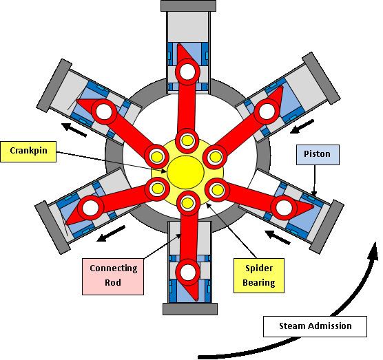
'Spider bearing'
The WHE-25 is designed with six connecting rods sharing one crankpin on the crankshaft. The standard design for such connection is with a master connecting rod connected to one piston and the remaining rods connected to pins in the big end of the master rod. Harry Schoell, inventor of the WHE, also invented what he called a 'spider bearing', which is a disk that can rotate around the crankpin, and has one bearing journal around its periphery for each of the six connecting rods. While this design eliminates the need for a separate master rod, it introduces one uncontrolled degree of freedom, i.e., the spider bearing itself can rotate in one direction until its motion is stopped by impacting with the connecting rods, then rotate in the other direction through some angle before it is stopped by again impacting connecting rods.
The WHE-DR design eliminated the spider bearing by having each cylinder offset from the others longitudinally so that the connecting rod big ends can fit on a shared crankpin side by side. It has been reported that "Initial testing has demonstrated significantly smoother and quieter operation." Elimination of the spider bearing was the only design change that would have led to this improvement.
Water lubrication
The Waste Heat Engine's design requires the use of water to lubricate the moving parts because exhaust steam goes into the engine crankcase. Any oil used to lubricate crankshaft and connecting rod bearings would soon form an emulsion of oil and water that would have very poor lubricating properties.
Journal bearings on the crankshaft and connecting rods and the pistons sliding in their cylinders operate in the hydrodynamic lubrication regime. The carrying capacity of a journal bearing is a direct function of the dynamic viscosity of the lubricating fluid. Water at 20 °C has a viscosity of 0.001002 Pa·s, while a typical motor oil could have a viscosity of about 0.250 Pa·s. Thus, water is about 250 times less effective of a lubricant than oil.
Cyclone Power Technologies had contracted with the Ohio State University Center for Automotive Research (OSU-CAR) for engineering analysis. A March 8, 2014 presentation by OSU-CAR described the engine bearings as a "critical path issue" and stated:
The contract between Cyclone Power Technologies and Phoenix Power Group for the WHE states that Phoenix Power Group will make a $150,000 progress payment "Upon the completion of 200 hours of durability testing of WHE version 5.0 as conducted and/or overseen by OSU. The durability testing shall consist of the WHE engine operating, without failure, and producing 10hp to 20hp". As of March 25, 2015 there has been no indication they have made a water lubricated engine pass this 200-hour endurance test.
Efficiency
No independent tests of any WHE model have been reported, but an indication comes from information published regarding the test waste heat recovery system for Bent Glass Design of Hatboro, PA. The system was described as providing up to 10 kW electrical output using a WHE-25 model engine and "will convert over 500,000 BTUs of exhaust heat from the customer's glass manufacturing furnaces into electric power." A heat flow rate 500,000 BTU/hr equals 146.5 kW.
The WHE-25 engine has a 34% cutoff. This allows for the remaining 66% of the piston stroke to expand the steam, extracting work from it and causing the pressure to drop. The figure to the right shows how pressure in the cylinder of a steam engine drops after the cutoff point. The WHE-DR must have a much later cutoff to allow it to self-start. The later cutoff leads to a larger mean effective pressure that will give a larger power output for an engine of a given size operating at a given speed, but also leads to a decrease in efficiency since steam is at a higher pressure when exhausted from the cylinder and less of its energy has been converted to mechanical work.
Auxiliary equipment
Expander: A steam engine is just one component in a Rankine cycle power system. The figure of the Rankine cycle at the right shows a turbine rather than a reciprocating piston engine between states 3 and 4, but either device acts as the expander stage in the cycle.
Condenser: The device between states 4 and 1 is the condenser. It removes heat from the engine exhaust steam to condense it back into water. In the case of the WHE-25 engine in the previous sub-section, of the 146.5 kW of heat energy supplied in the initial steam, 10 kW was converted into electricity. That leaves 146.5 - 10 = 136.5 kW of heat energy to be removed by the condenser. As a point of comparison, a Caterpillar C13 diesel engine that is commonly used in tractor-trailer trucks has a heat rejection to coolant rating of 128 kW. Thus, a condenser for the WHE-25 engine producing 10 kW of power would be about the size of the radiator on a semi-truck. The newer WHE-DR is likely less efficient, so would need an even bigger condenser for the same output power.
The condenser requires enough airflow to take away the heat. A fan is usually used to create this airflow, and its power consumption reduces the net power available from the system.
Feed water pump: The condensed water is stored in a tank, then pumped to high pressure by the feed water pump, states 1 to 2 in the figure. This pump requires a source of power, as well as a control system so that it pumps the proper amount of water to compensate for the amount of steam put into the engine.
Boiler: Heat is added to the water in the boiler to create the steam, states 2 to 3 in the figure. Boilers are sometimes called steam generators, and Cyclone Power Technologies has used the term "Combustion Chamber/Heat Exchanger" or "CCHX". Regardless of the name used, if the system pressure is greater than 15 psi (1 bar) and heat is added, the device is legally a boiler. All states in the United States except Idaho and Wyoming and all provinces in Canada have legally adopted the requirement for boilers to be registered with the National Board of Boiler and Pressure Vessel Inspectors. Registration includes the requirements that the boiler's design be approved as meeting the ASME Boiler and Pressure Vessel Code (BPVC), must be constructed in a facility currently authorized by ASME to construct such boilers, must be installed and tested to the approval of a National Board inspector, and, is required to undergo periodic inspections at the owner's expense.
The jurisdiction may also require the installation be operated by a licensed stationary engineer, as well as be covered by sufficient liability insurance.
The reason for such scrutiny is because of the catastrophic losses that can occur due to a boiler explosion.
A system will also require an approved steam safety valve and water level control as well as valves for water into the boiler and steam to the engine. If the system is intended to run without supervision, then sensors and automatic safety shutdown systems are needed.
Thus, the waste heat engine may be one of the least expensive components of a complete waste heat recovery system.