
 | ||
ElecronicBits #4: Current Feedback Amplifiers (CFA)
The current feedback operational amplifier (CFOA or CFA) is a type of electronic amplifier whose inverting input is sensitive to current, rather than to voltage as in a conventional voltage-feedback operational amplifier (VFA). The CFA was invented by David Nelson at Comlinear Corporation, and first sold in 1982 as a hybrid amplifier, the CLC103. An early patent covering a CFA is U.S. Patent 4,502,020, David Nelson and Kenneth Saller (filed in 1983). The integrated circuit CFAs were introduced in 1987 by both Comlinear and Elantec (designer Bill Gross). They are usually produced with the same pin arrangements as VFAs, allowing the two types to be interchanged without rewiring when the circuit design allows. In simple configurations, such as linear amplifiers, a CFA can be used in place of a VFA with no circuit modifications, but in other cases, such as integrators, a different circuit design is required. The classic four-resistor differential amplifier configuration also works with a CFA, but the common-mode rejection ratio is poorer than that from a VFA.
Contents
- ElecronicBits 4 Current Feedback Amplifiers CFA
- Operation
- VFA and CFA compared
- References
- Current feedback operational amplifier Wikipedia
Operation
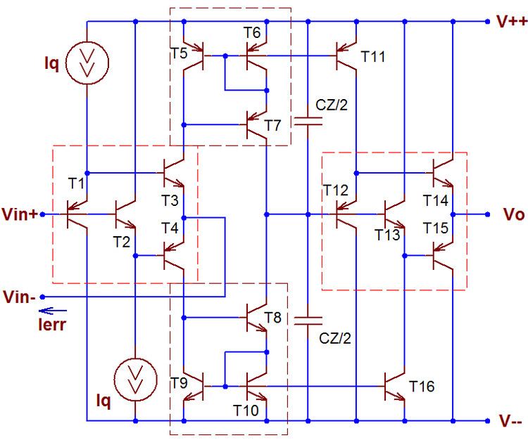
Referring to the schematic shown, the section marked in red forms the input stage and error amplifier. The inverting input (node where emitters of Q1 & Q2 are connected) is low-impedance and hence sensitive to changes in current. Resistors R1–R4 set up the quiescent bias conditions and are chosen such that the collector currents of Q1 & Q2 are the same. In most designs, active biasing circuitry is used instead of passive resistive biasing, and the non-inverting input may also be modified to become low impedance like the inverting input in order to minimise offsets.
With no signal applied, due to the current mirrors Q3/Q4 & Q5/Q6, the collector currents of Q4 and Q6 will be equal in magnitude if the collector currents of Q1 and Q2 are also equal in magnitude. Thus, no current will flow into the buffer's input (or equivalently no voltage will be present at the buffer's input). In practice, due to device mismatches the collector currents are unequal and this results in the difference flowing into the buffer's input resulting in an offset at its output. This is corrected by adjusting the input bias or adding offset nulling circuitry.
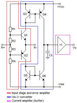
The section marked in blue (Q3–Q6) forms an I-to-V converter. Any change in the collector currents of Q1 and Q2 (as a result of a signal at the non-inverting input) appears as an equivalent change in the voltage at the junction of the collectors of Q4 and Q6. Cs is a stability capacitor to ensure that the circuit remains stable for all operating conditions. Due to the wide open-loop bandwidth of a CFA, there is a high risk of the circuit breaking into oscillations. Cs ensures that frequencies where oscillations might start are attenuated, especially when running with a low closed-loop gain.
The output stage (in magenta) is a buffer which provides current gain. It has a voltage gain of unity (+1 in the schematic).
VFA and CFA compared
Internally compensated VFA bandwidth is dominated by an internal dominant pole compensation capacitor, resulting in a constant gain/bandwidth limitation. CFAs, in contrast, have no dominant pole capacitor and therefore can operate much more closely to their maximum frequency at higher gain. Stated another way, the gain/bandwidth dependence of VFA has been broken.
In VFAs, dynamic performance is limited by the gain-bandwidth product and the slew rate. CFA use a circuit topology that emphasizes current-mode operation, which is inherently much faster than voltage-mode operation because it is less prone to the effect of stray node-capacitances. When fabricated using high-speed complementary bipolar processes, CFAs can be orders of magnitude faster than VFAs. With CFAs, the amplifier gain may be controlled independently of bandwidth. This constitutes the major advantages of CFAs over conventional VFA topologies.
Disadvantages of CFAs include poorer input offset voltage and input bias current characteristics. Additionally, the DC loop gains are generally smaller by about three decimal orders of magnitude. Given their substantially greater bandwidths, they also tend to be noisier. CFA circuits must never include a direct capacitance between the output and inverting input pins as this often leads to oscillation. CFAs are ideally suited to very high speed applications with moderate accuracy requirements.
Development of faster VFAs is ongoing, and VFAs are available with gain-bandwidth products in the low UHF range at the time of this writing. However, CFAs are available with gain-bandwidth products more than an octave higher than their VFA cousins and are also capable of operating as amplifiers very near their gain-bandwidth products.