
 | ||
Compressible Duct Flow with friction. This article concerns a gas flow with friction due to the boundary walls under consideration. This problem is same as the Moody type pipe-friction problem but with considerably larger changes in friction, kinetic energy and enthalpy of the flow.
Contents
Parameters
Consider a gas flowing through a duct with the following assumptions :
- Constant area, straight duct
- Gas is ideal
- Negligible potential energy changes and low work input
- One dimensional adiabatic flow
- Darcy friction factor used to express wall shear stress due to friction
Calculation
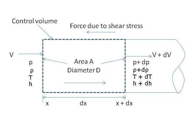
Consider a small element of area A and length dx as shown in the figure (right). Applying conservation laws on this element,
V-velocity of the element
A- cross sectional area
ρV A = G =constant
By equating total force on the element to its change in momentum (following Newton’s second law),
where
Total energy of the gas
Also by virtue of ideal gas equation
The relation between wall shear and Darcy friction factor f is given by,
But we know that
Therefore the above equation transforms into-
Where Ma is the Mach number which is defined as the ratio of velocity of sound in that medium to the velocity of the object under consideration i.e V/a.....(iii)
Thus from (i), (ii),(iii)
By eliminating variables from eq 1 to 6 we get the following relations:
All the equations above have a factor of
Irrespective of the flow,Mach number tends downstream towards 1 because entropy increases alongside. Entropy v/s Mach number graph is as shown in the figure (for k=1.4):
Entropy is maximum at Ma=1 so sonic point is eventually achieved by virtue of second law. Since
Now, By manipulating equation 11 and integrating bothsides we get,
L* is the length from some arbitrary point where Mach number is Ma. At the sonic region, Ma=1. The integration results in the following equation :
Where f- is average friction factor from x=0 to L*. Here D is the diameter of circular duct; in cases where the duct is not of circular cross section D=(4*area)/perimeter.
Choking due to friction
Choking of duct is basically reduction of duct mass flow. The flow conditions change if the actual length L is greater than the predicted maximum length L*, and there are two classifications :
Subsonic inlet
If L > L*(Ma1), the flow slows down until an inlet Mach number Ma2 is reached such that L = L*(Ma2). The exit flow is sonic, and the mass flow has been reduced by frictional choking. Further increases in duct length will continue to decrease the inlet Ma and mass flow.
Supersonic inlet
Friction have a very large impact on supersonic duct flow. Even an infinite inlet Mach number will be reduced to sonic conditions in only 41 diameters for f = 0.02. Let us consider an example inlet Ma = 3.0 and f=0.02. For this condition L*=26 di ameters. If L is increased beyond 26D, the flow will not choke but a normal shock will form at just the right place for the subsequent subsonic frictional flow to become sonic exactly at the exit. Eventually, a very long duct will cause the feednozzle throat to become choked, thus reducing the duct mass flow. Thus supersonic friction changes the flow pattern if L > L* but does not choke the flow until L is much larger than L*.