
 | ||
The commutation cell is the basic structure in power electronics. It is composed of an electronic switch (today a high-power semiconductor, not a mechanical switch) and a diode. It was traditionally referred to as a chopper, but since switching power supplies became a major form of power conversion, this new term has become more popular.
Contents
- Connection of two power elements
- The structure of a commutation cell
- The commutation cell in converters
- References
The purpose of the commutation cell is to "chop" DC power into square wave alternating current. This is done so that an inductor and a capacitor can be used in an LC circuit to change the voltage. This is in theory a lossless process, and in practice efficiencies above 80-90% are routinely achieved. The output is then usually run through a filter to produce clean DC power. By controlling the on and off times (the duty cycle) of the switch in the commutation cell, the output voltage can be regulated.
This basic principle is the core of most modern power supplies, from tiny DC-DC converters in portable devices to huge switching stations for high voltage DC power transmission.
Connection of two power elements
A Commutation cell connects two power elements, often referred to as sources, although they can either produce or absorb power.
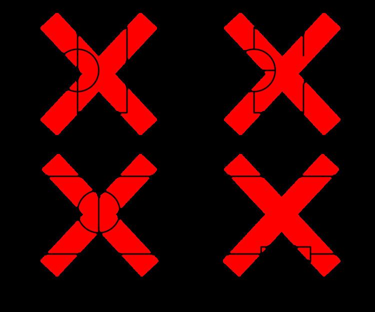
Some requirements to connect power sources exist. The impossible configurations are listed in figure 1. They are basically:
This applies to classical sources (battery, generator), but also to capacitors and inductors: At a small time scale, a capacitor is identical to a voltage source, and an inductor to a current source. Connecting two capacitors with different voltage level in parallel therefore corresponds to connecting two voltage sources, one of the forbidden connections of figure 1.
The figure 2 illustrates the poor efficiency of such connection. One capacitor is charged to a voltage V, and is connected to a capacitor with the same capacity, but discharged.
Before the connection, the energy in the circuit is
After the connection has been made, the quantity of charges is constant, and the total capacitance is
The same applies with the connections in series of two inductances. The magnetic flux (
As a result, it can be seen that a commutation cell can only connect a voltage source to a current source (and vice versa). However, using inductors and capacitors, it is possible to transform the behaviour of a source: for example two voltage sources can be connected through a converter if it uses an inductor to transfer energy.
The structure of a commutation cell
As told above, a commutation cell must be placed between a voltage source and a current source. Depending on the state of the cell, both sources are either connected, or isolated. When isolated, the current source must be shorted, as it is impossible for a current to be created in an open circuit. The basic schematic of a commutation cell is therefore given in figure 3 (top). It uses two switches with opposite states: In the configuration depicted in figure 3, both sources are isolated, and the current source is shorted. When the top switch is on (and the bottom switch is off), both sources are connected.
In reality, it is impossible to have a perfect synchronization between the switches. At one point during the commutation, they would be either both on (thus shorting the voltage source) or off (thus leaving the current source in an open circuit). This is why one of the switches has to be replaced by a diode. A diode is a natural commutation device, i.e. its state is controlled by the circuit itself. It will turn on or off at the exact moment it has to. The consequence of using a diode in a commutation cell is that it makes it unidirectional (see figure 3). A bidirectional cell can be built, but it is basically equivalent to two unidirectional cells connected in parallel.
The commutation cell in converters
The commutation cell can be found in any power electronic converter. Some examples are given in figure 4. As can be seen, a "current source" (actually a loop that contains an inductance) is always connected between the middle point and one of the external connections of the commutation cell, while a voltage source (or a capacitor, or a connection in series of voltage source and capacitor) is always connected to the two external connections.