
 | ||
Clerget was the name given to a series of early rotary aircraft engine types of the World War I era that were designed by Pierre Clerget. Manufactured in both France by Clerget-Blin and Great Britain by Gwynnes Limited they were used on such aircraft as the Sopwith Camel and Vickers Gunbus.
Contents
- Rotary engine development
- Design features
- Rotary engine types
- Rotary engines on display
- Radial X engines
- Diesel radial engines
- H 16 engine
- References
In the 1920s Pierre Clerget turned his attention to diesel radial engines and finally produced a H-16 engine before he died in 1943.
Rotary engine development
What distinguished the Clerget rotary engine from its rivals (Gnome and Le Rhône) was that the Clerget had normal intake and exhaust valves unlike the Gnome, and the connecting rod arrangement was much simpler than the Le Rhone. A source of failure among the Clerget engines were the special-purpose piston rings, called obturator rings. These were located below the gudgeon or wrist pin, to block heat transfer from the combustion area to the lower part of the cylinder and overcome their subsequent distortion. These rings were often made from brass and only had a lifespan of a few hours. The Clerget engines were considered reliable but they cost more per unit to produce than their rivals. Unlike other contemporary rotaries in which the ignition system was either switched on or off to provide a rudimentary form of engine speed control, the Clerget featured a throttle.
The Bentley BR1 and Bentley BR2 rotaries were designed as improvements of the Clerget, while sharing some of the earlier engine's distinctive design features.
Design features
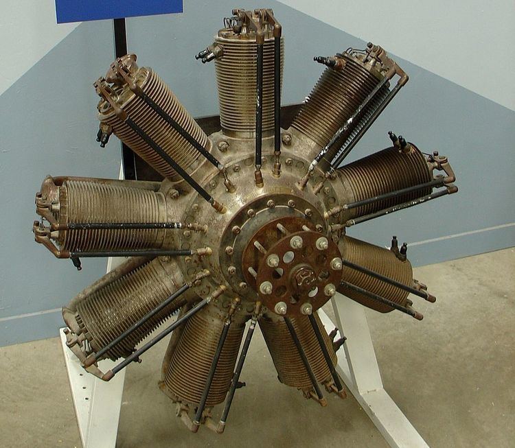
The Clerget rotary engines were air-cooled with either seven, nine or eleven cylinders. They were fitted with a double thrust ball race, which enabled them to be used either as a pusher or as a tractor engine.
The engines worked on a four-stroke cycle. The chief points of difference from other rotary engines were:
The direction of rotation was counter (anti)-clockwise as seen from the propeller-end of the engine. Between any two consecutive firing strokes, the engine turned through 80 degrees. Like many other rotary engines of the period they were made chiefly of steel, for strength and lightness.
Rotary engine types
Rotary engines on display
Radial 'X' engines
Diesel radial engines
In the 1920s Pierre Clerget designed static diesel radial engines, the earliest were based on his rotary designs.
(1929) 100 hp (75 kW) Nine-cylinder, single row radial engine.
(1937) 14-cylinder, two-row radial engine, flown in a Potez 25 biplane.
H-16 engine
Clerget's final engine design was an H-16 known as the Type Transatlantique. It developed 2,000 hp (1,500 kW) through the use of four turbochargers.