
 | ||
A circle-throw vibrating machine is a screening machine employed in processes involving particle separation. In particle processes screening refers to separation of larger from smaller particles in a given feed, using only the materials' physical properties. Circle throw machines have simple structure with high screening efficiency and volume. However it has limitations on the types of feed that can be processed smoothly. Some characteristics of circle-throw machines, such as frequency, vibration amplitude and angle of incline deck also affect output.
Contents
Applications
They are widely used for screening quarry stone stock and classifying products in mining, sand, gold, energy and chemical industrial processes. The targeted substance is predominantly finer particles, which can then be directed into a separation unit, such as a hydrocyclone or are materials that can be removed and used. Removed materials are often formed intentionally and are classified by their shape, size and physical properties. For example, construction wastes are sorted and sieved by a circular vibrating screen into coarse and fine particles. The particles are taken to make concrete, architectural bricks and road base materials.
Competitive processes
Circle-throw vibrating screens operate on an inclined surface. A deck moves in a circle. It operates with a continuous feed rather than in batches, leading to much greater output. The incline allows the feed to move through the device.
Circle-throw machines are larger than others, and may require greater space than other screening units. Fine, wet, sticky materials require a water spray to wash fine materials under spray bars. Circle-throws have a large stroke and allow heavy components to circulate and interfere with the screen box. A powerful motor is needed, while other separators may not.
Circle throw separation does not produce a separate waste stream. The feed is separated into multiple streams, with the number of exit streams matching the number of decks. Circle throw separation usually follows a grinding process. The coarser upper deck stream(s) can be directly re-fed into the grinding units due to continuous operation, thus reducing transport time, costs and storage.
Design
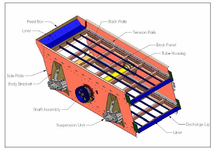
The standard unit is a single-shaft, double-bearing unit constructed with a sieving box, mesh, vibration exciter and damper spring. The screen framing is steel side plates and cross-members that brace static and dynamic forces. At the center of the side plates, two roller bearings with counterweights are connected to run the drive. Four sets of springs are fixed on the base of the unit to overcome the lengthwise or crosswise tension from sieves and panels and to dampen movement. An external vibration exciter (motor) is mounted on the lateral (side) plate of the screen box with a cylindrical eccentric shaft and stroke adjustment unit. At the screen outlet, the flows are changed in direction, usually to 90 degrees or alternate directions, which reduces the exiting stream speed. Strong, ring-grooved lock bolts connect components.
Variations in this design regard the positioning of the vibration components. One alternative is top mounted vibration, in which the vibrators are attached to the top of the unit frame and produce an elliptical stroke. This decreases efficiency in favor of increased capacity by increasing the rotational speed, which is required for rough screening procedures where a high flow rate must be maintained.
A refinement adds a counter-flow top mounting vibration, in which the sieving is more efficient because the material bed is deeper and the material stays on the screen for a longer time. It is employed in processes where higher separation efficiency per pass is required.
A dust hood or enclosure can be added to handle particularly loose particles. Water sprays may be attached above the top deck and the separation can be converted into a wet screening process.
Screen deck inclination angle
The circular-throw vibrating screen generates a rotating acceleration vector and the screen must maintain a steep throwing angle to prevent transportation along the screen deck. The deck is commonly constructed to have an angle within the range of 10° to 18°, in order to develop adequate particle movement. An Increase of deck angle speeds particle motion with proportional relationship to particle size. This decreases residence time and size stratification along the mesh screen. However, if the angle is greater than 20°, efficiency decreases due to reduction of effective mesh area. Effect of deck angle on efficiency is also influenced by particle density. In mining the optimal inclination angle is about 15°. Exceptions are the dewatering screens at 3° to 5° and steep screens at 20° to 40°.
Short distribution time
On average, 1.5 seconds is required for the screen process to reach a steady state and for particles to cover the screen. This is induced by the circular motion. The rotary acceleration has a loosening effect on the particles on the deck. Centrifugal forces spread particles across the screen. With the combination of the gravitational component, the efficiency of small particle passing through aperture is improved, and large size particles are carried forward towards the discharge end.
Vibration separation
Under vibration, particles of different sizes segregate (Brazil nut effect). Vibration lifts and segregates particles on the inclined screen. When vibration amplitude is within the range of 3 to 3.5mm, the equipment segregates the large and small particles with best efficiency. If the amplitude is too high, the contact area between particles and screen surface is reduced and energy is wasted; if too low, particles block the aperture, causing poor separation.
Higher frequency of vibration improves component stratification along the screen and leads to better separation efficiency. Circle throw gear is designed with 750 ~to 1050 rpm, which screens large materials. However, frequencies that are too high vibrate particles excessively; therefore the effective contact area of mesh surface to particles decreases.
Characteristics of feed
Moisture in the feed forms larger particles by coagulating small particles. This effect reduces sieve efficiency. However the centrifugal force and vibration and acts to prevent aperture blockage and agglomerated particle formation. Feed particles are classified as fine, near-sized and oversized particles; most near-sized and fines pass through the aperture rapidly. The ratio of fine and near-size particles to oversize should be maximized to obtain high screening rates.
Rate of feed is proportional to efficiency and capacity of screen; high feed rate reaches steady state and resultsn in better screening rates. However, an optimum bed thickness should be maintained for consistent high efficiency.
Stable efficiency
Steady state screening efficiency is sensitive to the vibration amplitude. Good screening performance usually occurs when the amplitude is 3-3.5 mm. Particle velocity should be no more than 0.389 m/s. If the speed is too big, poor segregation and low efficiency follows. Eo shows the efficiency of undersize removal from oversize at steady state.
where F is stph(short ton per hour) of feed ore, O is stph of oversize solids discharging as screen oversize, fx is cumulative weight fraction of feed finer than ‘x’ and ox is cumulative weight fraction of oversize finer than ‘x’. Eu shows the efficiency of undersize recovery. U is mass rate of solids in the undersize stream.
Thus
Vibration design
Circle-throw vibrating units rely on operating the screen component at a resonant frequency to sieve efficiently. While properly selected vibration frequencies drastically improve filtration, a deflection factor occurs as the vibrations displaces smaller particles. They do not properly pass through the screen due to excess movement. This is a property of the system's natural frequency. The natural frequency preferably vibrates at Fn is 188(1/d)2 (cycles per min) where d = (188/Fn)2 (inches). Static deflection corresponds to this frequency. Vibration isolation is a control principle employed to mitigate transmission. On circle-throw vibrating screens, passive vibration isolation in the form of mechanical springs and suspension are employed at the base of the unit, which provides stability and control of motor vibration. A rule of thumb regarding the amount of static deflection minimization that should be targeted with respect to operating RPM is provided in the table below.
Critical installations refer to roof-mounted units. Weight, loading and weight distribution are all elements which must be considered.
Roller bearing design
A circle-throw vibrating screen with a shaft and bearing system requires consideration of the loading the unit will undergo. The extra loading to the screen box created by the centrifugal force, due to the circular motion of the load as it passes through the unit is also a factor. Bearings must be designed to accommodate the extra stress. Bearing load due to screen box centrifugal force (Fr) is
Supplementary factor of Fz = ~1.2 is used to account for unfavorable dynamic stressing:
Index of dynamic stressing FL, speed factor Fn are used to calculate minimum required dynamic loading (kN)
FL is taken between 2.5-3 generally as to correspond to a nominal fatigue life of 11,000-20,000 hours as part of a usual design.
Structural support of vibrating equipment
The unit's processing ability is related to the vibration, requiring care to the design of the structural and support elements. An inadequate structural design is unable to stabilize the unit producing excess vibrations, leading to higher deflection or reducing effectiveness.
Total static force applied and spring stiffness:
When the dynamic forces of the loading is considered, an amplitude magnification factor (MF) must be considered:
An estimation of the magnification factor for a system with one degree of freedom may be gained using:
Most structural mechanical systems are lightly damped. If the damping term is neglected:
where fd/fn represents frequency ratio (frequency due to dynamic force, fd, and natural frequency of the unit, fn).
Screen length/width
Once the area of the unit is known, the screen's length and width must be calculated so that a ratio of 2-3 width(W) to 1 length (L) is maintained. Capacity is controlled by width adjustment and efficiency by width.
The bed depth D must be lesser or equal to
Xs is desired cut size.
Starting deck angles can be estimated from
F= ideal oversize flowrate, standard widths for circle-throw machines are 24,36,48,60, 72, 84, 96 inches. Measurements should be matched to available "on-shelf" units to reduce capital cost.
Aperture size and shape
At a fixed screen capacity, efficiency is likely to decrease as aperture size decreases. In general, particles are not required to be separated precisely at their aperture size. However efficiency is improved if the screen is designed to filter as close to the intended cut size as possible. The selection of aperture type is generalized by the table below:
Bearings
Most processes have employed two-bearing screens. Two- bearing circular vibrating screens with a screen box weight of 35 kN and speed of 1200 RPM were common. The centroid axis of the screen box and unbalanced load does not change during rotation.
A four-bearing vibrating screen (F- Class) was developed to meet demands especially for iron ore, phosphate and limestone production industries. F-Class features a HUCK-bolted screen body is connected for extra strength and rigidity and carbon steel is used for the side plates to give high strength. The shaft is strengthened with a reinforcing plate, which attaches to the slide plate and screen panels.
Four-bearing screen provide much greater unit stability thus higher vibration amplitudes and/or frequencies may be used without excess isolation or dampening; overall plant noise emission. The new design gives an accurate, fast sizing classification with materials ranging in cut size from 0.15 to 9.76 inches and high tonnage output that can process up to 5000 tons per hour.