
 | ||
A chuck is a specialized type of clamp. It is used to hold an object with radial symmetry, especially a cylinder. In drills and mills it holds the rotating tool whereas in lathes it holds the rotating workpiece. On a lathe the chuck is mounted on the spindle which rotates within the headstock. For some purposes (such as drilling) an additional chuck may be mounted on the non-rotating tailstock.
Contents
- Self centering
- Independent jaw
- Specialty jawed types two six eight jaw other
- Jaw construction
- Collet
- Special Direct System SDS
- Chucks with both indexable positioning and indexable clamping
- Magnetic
- Electrostatic
- Vacuum
- Mounting methods
- Mounting of drill chucks
- Mounting of large jawed chucks
- Mounting of collet chucks
- History
- Performance Evaluation
- References
Many chucks have jaws, (sometimes called dogs) that are arranged in a radially symmetrical pattern like the points of a star. The jaws are tightened up to hold the tool or workpiece. Often the jaws will be tightened or loosened with the help of a chuck key, which is a wrench-like tool made for the purpose. Many jawed chucks, however, are of the keyless variety, and their tightening and loosening is by hand force alone. Keyless designs offer the convenience of quicker and easier chucking and unchucking, but have lower gripping force to hold the tool or workpiece, which is potentially more of a problem with cylindrical than hexagonal shanks. Some lathe chucks have independently moving jaws which can also hold irregularly shaped objects (ones that lack radial symmetry). Collet chucks, rather than having jaws, have collets, which are flexible collars or sleeves that fit closely around the tool or workpiece and grip it when squeezed. A few chuck designs are more complex yet, and they involve specially shaped jaws, higher numbers of jaws, quick-release mechanisms, or other special features.
Some chucks, such as magnetic chucks and vacuum chucks, are of a different sort from the radially symmetrical mechanical clamps mentioned above. Instead, they may be surfaces (typically flat) against which workpieces or tools are firmly held by magnetic or vacuum force.
To chuck a tool or workpiece is to hold it with a chuck, in which case it has been chucked. Lathe work whose workholding involves chucking individual slugs or blanks is often called chucking work, in contrast to bar work or bar feed work. In bar work the bar protrudes from the chuck, is worked upon, then cut off by a lathe tool (parted off) rather than being sawn off. Automatic lathes that specialize in chucking work are often called chuckers.
Self-centering
A self-centering chuck, also known as a scroll chuck, uses dogs (usually called jaws), interconnected via a scroll gear (scroll plate), to hold onto a tool or workpiece. Because they most often have three jaws, the term three-jaw chuck without other qualification is understood by machinists to mean a self-centering three-jaw chuck. The term universal chuck also refers to this type. These chucks are best suited to grip circular or hexagonal cross-sections when very fast, reasonably accurate (±0.005 inch [0.125 mm] TIR) centering is desired.
Sometimes this type of chuck has 4 or 6 jaws instead of 3. More jaws grip the workpiece more securely if it is truly cylindrical, and thin-walled work will deform less. Four jaws are also useful for square bar work.
There are also independent-jaw (non-self-centering) chucks with three jaws.
There are hybrid self-centering chucks that have adjustment screws that can be used to further improve the concentricity after the workpiece has been gripped by the scroll jaws. This feature is meant to combine the speed and ease of the scroll plate's self-centering with the run-out eliminating controllability of an independent-jaw chuck. The most commonly used name for this type is a brand name, Set-Tru. To avoid undue genericization of that brand name, suggestions for a generic name have included "exact-adjust".
Three-jaw chucks are often used on lathes and indexing heads.
Drill chuck
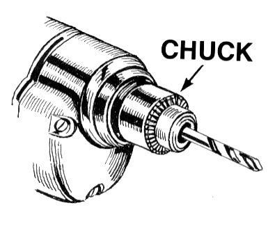
A drill chuck is a specialised self-centering, three-jaw chuck, usually with capacity of 0.5 in (13 mm) or less and rarely greater than 1 in (25 mm), used to hold drill bits or other rotary tools. This type of chuck is used on tools ranging from professional equipment to inexpensive hand and power drills for domestic use; it is the type a person who does not normally work with machine tools is most likely to be familiar with.
Some high-precision chucks use ball thrust bearings to reduce friction in the closing mechanism and maximize drilling torque. One brand name for this type of chuck, which is often genericized in colloquial use although not in catalogs, is Super Chuck.
A pin chuck is a specialized chuck designed to hold small drills (less than 1 mm (0.039 in) in diameter) that could not be held securely in a normal drill chuck. The drill is inserted into the pin chuck and tightened; the pin chuck has a shaft which is then inserted into the larger drill chuck to hold the drill securely. Pin chucks are also used with high-speed rotary tools other than drills, such as die grinders and jig grinders.
Independent-jaw
On an independent-jaw chuck, each jaw can be moved independently. Because they most often have four jaws, the term four-jaw chuck without other qualification is understood by machinists to mean a chuck with four independent jaws. The independence of the jaws makes these chucks ideal for (a) gripping non-circular cross sections and (b) gripping circular cross sections with extreme precision (when the last few hundredths of a millimeter [or thousandths of an inch] of runout must be manually eliminated). The non-self-centering action of the independent jaws makes centering highly controllable (for an experienced user), but at the expense of speed and ease. Four-jaw chucks are almost never used for tool holding. Four-jaw chucks can be found on lathes and indexing heads.
Self-centering chucks with four jaws also can be obtained. Although these are often said to suffer from two disadvantages: inability to hold hex stock, and poor gripping on stock which is oval, only the latter is true. Even with three jaw self centering chucks, work which is not of uniform section along the work (and which is not free of spiral or 'wind')should not be gripped, as the jaws can be strained and the accuracy permanently impaired.
Four-jaw chucks can easily hold a workpiece eccentrically if eccentric features need to be machined.
Spiders
A spider is a simple, relatively inexpensive, limited-capability version of an independent-jaw chuck. It typically consists of a ring of metal with screw threads tapped radially into it, in which screws (hex cap, socket hex cap, or set screws) serve as independent jaws. Spiders can serve various purposes:
Specialty jawed types (two-, six-, eight-jaw; other)
For special purposes, and also the holding of fragile materials, chucks are available with six or eight jaws. These are usually of the self-centering design, and may be built to very high standards of accuracy.
Two-jaw chucks are available and can be used with soft jaws (typically an aluminium alloy) that can be machined to conform to a particular workpiece. It is a short conceptual leap from these to faceplates holding custom fixtures, wherein the part is located against fixed stops and held there with toggle clamps or toe clamps.
Jaw construction
Many chucks have removable jaws (often the top part is removable leaving the base or 'master jaw' assembled with the scroll), which allows the user to replace them with new jaws, specialized jaws, or soft jaws. Soft jaws are made of soft materials such as soft (unhardened) metal, plastic, or wood. They can be machined as needed for particular setups. The typical interface between the master jaw and the removable jaw is a matching pair of serrated surfaces, which, once clamped by the mounting screws, cannot allow relative slipping between the two parts.
Collet
A collet, one type of chuck, is a sleeve with a (normally) cylindrical inner surface and a conical outer surface. The collet can be squeezed against a matching taper such that its inner surface contracts to a slightly smaller diameter, squeezing the tool or workpiece whose secure holding is desired. Most often this is achieved with a spring collet, made of spring steel, with one or more kerf cuts along its length to allow it to expand and contract. An alternative collet design is one that has several tapered steel blocks (essentially tapered gauge blocks) held in circular position (like the points of a star, or indeed the jaws of a jawed chuck) by a flexible binding medium (typically synthetic or natural rubber). The Jacobs Rubber-Flex brand is a name that most machinists would recognize for this type of collet chuck system.
Regardless of the collet design, the operating principle is the same: squeeze the collet radially against the tool or workpiece to be held, resulting in high static friction. Under correct conditions, it holds quite securely. Almost all collet chucks achieve the radial squeezing motion via moving one or more male-female pairs of tapered (conical) surfaces axially, which produces the radial squeezing in a highly concentric manner. Depending on the collet design, it can be either pulled (via a threaded section at the rear of the collet) or pushed (via a threaded cap with a second taper) into a matching conical socket to achieve the clamping action. As the collet is forced into the tapered socket, the collet will contract, gripping the contents of the inner cylinder. (The axial movement of cones is not mandatory, however; a split bushing squeezed radially with a linear force—e.g., set screw, solenoid, spring clamp, pneumatic or hydraulic cylinder—achieves the same principle without the cones; but concentricity can only be had to the extent that the bushing's diameters are perfect for the particular object being held. Thus only in toolroom contexts, such as machine tool tooling creation and setup, is this common.)
One of the corollaries of the conical action is that collets may draw the work axially a slight amount as they close. Collet chuck systems that make no provision to prevent this draw-in are often called draw-in collet chucks, in contrast to systems which circumvent this movement, usually by pushing the tapered closing ring toward the collet rather than pulling the collet into the ring. Such non-draw-in types are often called "dead-length" or "non-draw-in" collet chucks. Draw-in is not always a problem, but avoiding it can be helpful on some work where failing to account for it might result in inaccuracy on part overall length, shoulder lengths, etc.
Collets are most commonly found on milling machines, lathes, wood routers, precision grinders, and certain handheld power tools such as die grinders and rotary tools. There are many different systems, common examples being the ER, 5C, and R8 systems. Collets can also be obtained to fit Morse or Brown and Sharpe taper sockets.
Typically collets offer higher levels of precision and accuracy than self-centering chucks, and have a shorter setting up time than independent-jaw chucks. The penalty is that most collets can only accommodate a single size of workpiece. An exception is the ER collet which typically has a working range of 1 mm (about 0.04 in).
Collets usually are made to hold cylindrical work, but are available to hold square, hexagonal or octagonal workpieces. While most collets are hardened, "emergency" collets are available that can be machined to special sizes or shapes by the user. These collets can be obtained in steel, brass, or nylon. Step collets are available that are machinable to allow holding of short workpieces that are larger than the capacity of normal collets.
Special Direct System (SDS)
Developed by Bosch in 1975 for hammer drills, the SDS System uses an SDS Shank which is a cylindrical shank with indentations to be held by the chuck. A tool is inserted into the chuck by pressing in, and is locked in place until a separate lock release is used. The rotary force is supplied through wedges that fit into two or three open grooves. The hammer action actually moves the bit up and down within the chuck since the bit is free to move a short distance. Two sprung balls fit into closed grooves, allowing movement whilst retaining the bit. SDS relies on a tool having the same shank diameter as the chuck; there are three standard sizes:
Many SDS drills have a "rotation off" setting, which allows the drill to be used for chiselling. The name SDS comes from the German steck, dreh, sitzt (insert, twist, fits). German-speaking countries may use Spannen durch System (Clamping System), though Bosch uses Special Direct System for international purposes.
Chucks with both indexable positioning and indexable clamping
Commercial production machining now makes use of increasingly advanced chucks which have not only indexable positioning but also indexable clamping. Both functions are typically hydraulically controlled. The clamping is often done with each pair of jaws consisting of one fixed jaw and one movable jaw (hydraulically actuated), thematically similar to advanced milling vises. This method of clamping brings the high precision and repeatability of such vises to a chucking application. Such chucks offer the centering precision of traditional independent-jaw chucks with the chucking speed and ease of traditional three-jaw self-centering scroll chucks. They have expensive initial cost (compared with traditional chucks), but such initial cost pays for itself and then lowers ongoing marginal costs in commercial production-run environments.
It is also possible nowadays to build CNC chucks in which the position and clamping pressure of each jaw can be precisely controlled with CNC, via closed-loop positioning and load monitoring. In essence, each jaw is one independent CNC axis, a machine slide with a leadscrew, and all four or six of them can act in concert with each other. Although this idea is conceptually interesting, the simpler chucking systems mentioned in the previous paragraph are probably a marketplace winner over this alternative for most applications, because they supply the same capabilities via a simpler, less expensive solution.
Magnetic
Used for holding ferromagnetic workpieces, a magnetic chuck consists of an accurately centred permanent magnet face. Electromagnets or permanent magnets are brought into contact with fixed ferrous plates, or pole pieces, contained within a housing. These pole pieces are usually flush with the housing surface. The part (workpiece) to be held forms the closing of the magnetic loop or path, onto those fixed plates, providing a secure anchor for the workpiece.
Electrostatic
Commonly used for holding silicon wafers during lithography processes, an electrostatic chuck comprises a metal base-plate and a thin dielectric layer; the metal base-plate is maintained at a high-voltage relative to the wafer, and so an electrostatic force clamps the wafer to it. Electrostatic chucks may have pins, or mesas, the height of which is included in the reported dielectric thickness; a design by Sandia National Laboratory uses a patterned silicon-dioxide dielectric to form the pins.
Vacuum
A vacuum chuck is primarily used on non-ferrous materials, such as copper, bronze, aluminium, titanium, plastics, and stone. In a vacuum chuck, air is pumped from a cavity behind the workpiece, and atmospheric pressure provides the holding force. Vacuum produces a hold down pressure of 14.7 psi (101 kPa) at sea level, decreasing at higher elevations where the atmospheric pressure is lower. The decrease in holding pressure is roughly 0.5 psi per 1000' above sea level.
Mounting methods
Connecting chucks to the spindles or tables of machine tools or power tools has been accomplished in many ways over the years.
Mounting of drill chucks
Mounting of large jawed chucks
Mounting of collet chucks
History
The original forms of workholding on lathes were between-centers holding and ad hoc fastenings to the headstock spindle. The spike-style centers still used on wood lathes represent an ancient method. Ad hoc fastening methods in centuries past included anything from pinning with clenching or wedging; nailing; lashing with cords of leather or fiber; dogging down (again involving pinning/wedging/clenching); or other types. Faceplates have probably been around at least since the era of medieval clock-makers.
Tooling similar to today's chucks seems likely to have evolved from faceplate work, as workers using faceplates for repetitive work began to envision types of clamps or dogs for the faceplate that could be opened and closed in more convenient ways than repeated total disassembly and reassembly. A chock was originally just a lump of wood. However by 1703 it could be "… Chocks, belonging to the Screw-Mandrel". By 1807 the word had changed to the more familiar 'chuck: "On the end of the spindle … is screwed … a unversal Chuck for holding any kind of work".
In late 1818 or early 1819 the Society for the Encouragement of Arts, Manufactures and Commerce awarded its silver medal and 10 guineas (£10.50 – equivalent to £718 in 2015) to Mr. Alexander Bell for a three jaw lathe chuck:
The instrument can be screwed into … the mandrel of a lathe, and has three studs projecting from its flat surface, forming an equi-lateral triangle, and are capable of being moved equably to, or from, its centre.
It is not clear how they were moved "equably" whether by a scroll or some other means. Later in 1819 the same body awarded a further silver medal to Mr. T. Hack for a four jaw chuck.
Names known to figure in the history of chuck development include those of Simon Fairman (1792–1857) and his son-in-law Austin F. Cushman (1830–1914), and Arthur Irving Jacobs. Fairman invented the piece of tooling that we today would call a scroll chuck, and Cushman developed and sold this design under his business, Cushman Industries. Judging from a historical sketch given by the Jacobs Chuck Manufacturing Company (a well-known brand in the drill chuck field), Arthur I. (A.I.) Jacobs was apparently the person who further developed Cushman's self-centering scroll-gear idea into the type of drill chuck known today (for which his company would later become famous). A.I. Jacobs's patent of 1902 (U.S. Patent 709,014) appears to be the principal patent. The term "drill chuck" clearly did not originate with him, but his new type of drill chuck evidently long ago displaced any earlier types that lacked the angled jaw movement and outer sleeve now found on all common drill chucks.
Performance Evaluation
National and international standards are used to standardize the definitions, requirements, and test methods used for the performance evaluation of chucks. Selection of the standard to be used is an agreement between the supplier and the user and has some significance in the design of the chuck. In the United States, ASME has developed the B5.60 Standard entitled Workholding Chucks: Jaw-Type Chucks, which establishes requirements and methods for specifying and testing the performance of workholding chucks used primarily in turning operations.