
 | ||
Channel sounding is a technique that evaluates the radio environment for wireless communication, especially MIMO systems. Because of the effect of terrain and obstacles, wireless signals propagate in multiple paths (the multipath effect). To minimize or use the multipath effect, engineers use channel sounding to process the multidimensional spatial-temporal signal and estimate channel characteristics. This helps simulate and design wireless systems.
Contents
Motivation & applications
Mobile radio communication performance is significantly affected by the radio propagation environment. Blocking by buildings and natural obstacles creates multiple paths between the transmitter and the receiver, with different time variances, phases and attenuations. In a single-input, single-output (SISO) system, multiple propagation paths can create problems for signal optimization. However, based on the development of multiple input, multiple output (MIMO) systems, it can enhance channel capacity and improve QoS. In order to evaluate effectiveness of these multiple antenna systems, a measurement of the radio environment is needed. Channel sounding is such a technique that can estimate the channel characteristics for the simulation and design of antenna arrays.
Problem statement & basics
In a multipath system, the wireless channel is frequency dependent, time dependent, and position dependent. Therefore, the following parameters describe the channel:
To characterize the propagation path between each transmitter element and each receiver element, engineers transmit a broadband multi-tone test signal. The transmitter's continuous periodic test sequence arrives at the receiver, and is correlated with the original sequence. This impulse-like auto correlation function is called channel impulse response (CIR). By obtaining the transfer function of CIR, we can make an estimation of the channel environment and improve the performance.
MIMO Vector Channel Sounder
Based on multiple antennas at both transmitters and receivers, a MIMO vector channel sounder can effectively collect the propagation direction at both end of connection and significantly improve resolution of the multiple path parameters.
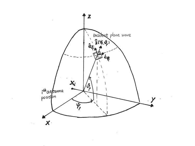
K-D model of wave propagation
Engineers model wave propagation as a finite sum of discrete, locally planar waves instead of a ray tracing model. This reduces computation and lowers requirements for optics knowledge. The waves are considered planar between the transmitters and the receivers. Two other important assumptions are:
Based on such assumptions, the basic signal model is described as:
where
Real-Time Ultra-wideband MIMO Channel Sounding
A higher bandwidth for channel measurement is a goal for future sounding devices. The new real-time UWB channel sounder can measure the channel in a larger bandwidth from near zero to 5 GHz. The real time UWB MIMO channel sounding is greatly improving accuracy of localization and detection, which facilitates precisely tracking mobile devices.
Excitation signal
A multitoned signal is chosen as the excitation signal.
where
Data post-processing
- A DFT over K-1 (one waveform lost due to array switching) waveforms that measured in each channel is performed (K: waveforms per channel).
- The frequency domain samples at the multitone frequencies are picked at every
( K − 1 ) t h - An estimated channel transfer function
H ^ ( f ) is obtained by:
where
RUSK Channel Sounder
A RUSK channel sounder excites all frequencies simultaneously, so that the frequency response of all frequencies can be measured. The test signal is periodic in time with period