
 | ||
Cephalometric analysis is the clinical application of cephalometry. It is analysis of the dental and skeletal relationships of a human skull. It is frequently used by dentists, orthodontists, and oral and maxillofacial surgeons as a treatment planning tool. Two of the more popular methods of analysis used in orthodontology are the Steiner analysis, named after Cecil C. Steiner, and Down's Analysis. There are other methods as well which are listed below.
Contents
- Cephalometric radiographs
- Lateral cephalometric radiographs
- Posteroanterior P A cephalometric radiograph
- Cephalometric tracing
- Cephalometric landmarks
- Classification of analyses
- Cephalometric angles
- Steiners Analysis
- WITS Analysis
- Bjorks Analysis
- Tweeds Analysis Triangle
- Jaraback Analysis
- Sassouni Analysis
- Harvold Analysis
- COGS Analysis Cephalometric for Orthognathic Surgery
- Computerised cephalometrics
- Digitization
- References
Cephalometric radiographs
Cephalometric analysis depends on cephalometric radiography to study relationships between bony and soft tissue landmarks and can be used to diagnose facial growth abnormalities prior to treatment, in the middle of treatment to evaluate progress or at the conclusion of treatment to ascertain that the goals of treatment have been met. A Cephalometric radiograph is a radiograph of the head taken in a Cephalometer (Cephalostat) that is a head-holding device introduced in 1931 by Holly Broadbent Sr. in USA. The Cephalometer is used to obtain standardized and comparable craniofacial images on radiographic films.
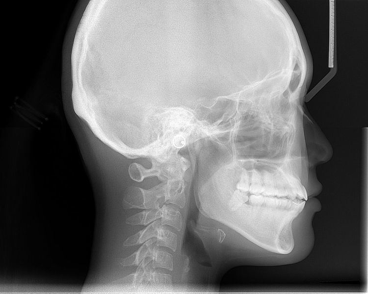
Lateral cephalometric radiographs
Lateral cephalometric radiograph is a radiograph of the head taken with the x-ray beam perpendicular to the patient's sagittal plane. Natural head position is a standardized orientation of the head that is reproducible for each individual and is used as a means of standardization during analysis of dentofacial morphology both for photos and radiographs. The concept of Natural head position was introduced by Coenraad Moorrees and M. R Kean in 1958 and now is a common method of head orientation for cephalometric radiography.
Registration of the head in its natural position while obtaining a cephalogram has the advantage that an extracranial line (the true vertical or a line perpendicular to that) can be used as a reference line for cephalometric analysis, thus bypassing the difficulties imposed by the biologic variation of intracranial reference lines. True vertical is an external reference line, commonly provided by the image of a free-hanging metal chain on the cephalostat registering on the film or digital cassette during exposure. The true vertical line offers the advantage of no variation (since it is generated by gravity) and is used with radiographs obtained in natural head position.
Posteroanterior (P-A) cephalometric radiograph
A radiograph of the head taken with the x-ray beam perpendicular to the patient’s coronal plane with the x-ray source behind the head and the film cassette in front of the patient’s face. PA ceph can be evaluated by following analyses that have been developed through the years:
Cephalometric tracing
A Cephalometric tracing is an overlay drawing produced from a cephalometric radiograph by digital means and a computer program or by copying specific outlines from it with a lead pencil onto acetate paper, using an illuminated view-box. Tracings are used to facilitate cephalometric analysis, as well as in superimpositions, to evaluate treatment and growth changes. Historically, tracings of the cephalometric radiographs are done on an 0.003 inch thick matte acetate paper by using a #3 pencil. The process is started by marking three registration crosses on the radiograph which are then transferred to the acetate paper.
Anatomical structures are traced first and some structures are bilateral and have tendency to show up as two separate lines, should have an "average" line drawn which is represented as a broken line. These landmarks could include inferior border of mandible.
Cephalometric landmarks
The following are important cephalometric landmarks.[definition needed] (Sources: Proffit; others.)
Landmark points can be joined by lines to form axes, vectors, angles, and planes (a line between 2 points can define a plane by projection). For example, the sella (S) and the nasion (N) together form the sella-nasion line (SN or S-N). A prime symbol (′) usually indicates the point on the skin's surface that corresponds to a given bony landmark (for example, nasion (N) versus skin nasion (N′).
Below is a list of cephalometric planes that are commonly used in different cephalometric analyses.
Classification of analyses
The basic elements of analysis are angles and distances. Measurements (in degrees or millimetres) may be treated as absolute or relative, or they may be related to each other to express proportional correlations. The various analyses may be grouped into the following:
- Angular – dealing with angles,
- Linear – dealing with distances and lengths,
- Coordinate – involving the Cartesian (X, Y) or even 3-D planes,
- Arcial – involving the construction of arcs to perform relational analyses.
These in turn may be grouped according to the following concepts on which normal values have been based:
- Mononormative analyses: averages serve as the norms for these and may be arithmetical (average figures) or geometrical (average tracings). E.g. Bolton Standards.
- Multinormative: for these a whole series of norms are used, with age and sex taken into account, e.g. Bolton Standards.
- Correlative: used to assess individual variations of facial structure to establish their mutual relationships, e.g. Sassouni’s arcial analysis.
Cephalometric angles
According to the Steiner's analysis:
SNA and SNB is important to determine what type of intervention (on maxilla, mandible or both) is appropriate. These angles, however are influenced also by the vertical height of the face and a possible abnormal positioning of nasion. By using a comparative set of angles and distances, measurements can be related to one another and to normative values to determine variations in a patient’s facial structure.
Steiner's Analysis
Cecil C. Steiner developed Steiner Analysis in 1953. He used S-N plane as his reference line in comparison to FH plane due to difficulty in identifying the orbitale and porion. Some of the drawbacks of Steiner's analysis includes its reliability on the point nasion. Nasion as a point is known not to be stable due to its growth early in life. Therefore, a posteriorly positioned nasion will increase ANB and more anterior positioned nasion can decrease ANB. In addition, short S-N plane or stepper S-N plane can also lead to greater numbers of SNA, SNB and ANB which may not reflex the true position of the jaws compare to the cranial base. In addition, clockwise rotation of both jaws can increase ANB and counter-clockwise rotation of jaws can decrease ANB.
WITS Analysis
Wits is short for Witwatersrand which is a University in South Africa. Jacobsen in 1975 published an article called "The Wits appraisal of jaw disharmony". This analysis was created as a diagnostic aid to measure the disharmony between the AP degree. The ANB angle can be affected by multitude of environmental factors such as:
- Patient's age where ANB has tendency to reduced with age
- Change in position of nasion as pubertal growth takes place
- Rotational effect of jaws
- Degree of facial Prognathism
Therefore, it measured the AP positions of the jaw to each other. This analysis calls for 1. Drawing an Occlusal Plane through the overlapping cusps of Molars and Premolars. 2. Draw perpendicular lines connecting A point and B Point to the Occlusal Plane 3. Label the points as AO and BO.
In his study, Jacobsen mentioned that average jaw relationship is -1mm in Males (AO is behind BO by 1mm) and 0mm in Females (AO and BO coincide). It's clinical significance is that in a Class 2 skeletal patient, AO is located ahead of BO. In skeletal Class 3 patient, BO is located ahead of AO. Therefore, the greater the wits reading, the greater the jaw discrepancy.
Drawbacks to Wits analysis includes:
Bjork's Analysis
This analysis by Arne Bjork was developed in 1947 based on 322 Swedish boys and 281 conscripts. He introduced a facial polygon which was based on 5 angles and is listed below. Bjork also developed the 7 structural signs which indicates the mandibular rotator type.
Tweed's Analysis (Triangle)
Charles H. Tweed developed his analysis in the year 1966. In this analysis, he tried describing the lower incisor position in relation to the basal bone and the face. This is described by 3 planes. He used Frankfurt Horizontal plane as a reference line.
Jaraback Analysis
Analysis developed by Joseph Jarabak in 1972. The analysis interprets how the craniofacial growth may affect the pre and post treatment dentition. The analysis is based on 5 points: Nasion (Na), Sella (S), Menton (Me), Go (Gonion) and Articulare (Ar). They together make a Polygon on a face when connected with lines. These points are used to study the anterior/posterior facial height relationships and predict the growth pattern in the lower half of the face. Three important angles used in his analysis are: 1. Saddle Angle - Na, S, Ar 2. Articular Angle - S-Ar-Go, 3. Gonial Angle - Ar-Go-Me.
In a patient who has a clockwise growth pattern, the sum of 3 angles will be higher than 396 degrees. The ratio of posterior height (S-Go) to Anterior Height (N-Me) is 56% to 44%. Therefore, a tendency to open bite will occur and a downward, backward growth of mandible will be observed.
Ricketts Analysis
Rickett's analysis also consists of following measurements
Sassouni Analysis
This analysis, developed by Viken Sassouni in 1955, states that in a well proportioned face, the following four planes meet at the point O. The point O is located in the posterior cranial base.This method categorized the vertical and the horizontal relationship and the interaction between the vertical proportions of the face.The planes he created are:
- Palatal Plane (ANS-PNS)
- Occlusal Plane (Down's occlusal plane)
- Mandibular Plane (Go-Me)
- Plane parallel inferior border of sella and is parallel to supraorbital plane
- Supraorbital plane (Anterior clenoid to roof of orbits)
The more parallel the planes, the greater the tendency for deep bite and the more non-parallel they are the greater the tendency for open bite. Using the O as the centre, Sassouni created the following arcs
Harvold Analysis
This analysis was developed by Egil Peter Harvold in 1974. This analysis developed standards for the unit length of the maxilla and mandible. The difference between the unit length describes the disharmony between the jaws. It is important to know that location of teeth is not taken into account in this analysis.
The maxillary unit length is measured from posterior border of mandibular condyle (Co) to ANS. The mandibular unit length is measured from posterior border of mandibular condyle (Co) to Pogonion. This analysis also looks at the lower facial height which is from upper ANS to Menton.
COGS Analysis (Cephalometric for Orthognathic Surgery)
This analysis was developed by Charles J. Burstone when it was presented in 1978 in an issue of AJODO. This was followed by Soft Tissue Cephalometric Analysis for Orthognathic Surgery in 1980 by Arnette et al. In this analysis, Burstone et al. used a plane called horizontal plane, which was a constructed of Frankfurt Horizontal Plane.
Computerised cephalometrics
Computerised cephalometrics is the process of entering cephalometric data in digital format into a computer for cephalometric analysis. Digitization (of radiographs) is the conversion of landmarks on a radiograph or tracing to numerical values on a two- (or three-) dimensional coordinate system, usually for the purpose of computerized cephalometric analysis. The process allows for automatic measurement of landmark relationships. Depending on the software and hardware available, the incorporation of data can be performed by digitizing points on a tracing, by scanning a tracing or a conventional radiograph, or by originally obtaining computerized radiographic images that are already in digital format, instead of conventional radiographs. Computerized cephalometrics offers the advantages of instant analysis; readily available race-, sex- and age-related norms for comparison; as well as ease of soft tissue change and surgical predictions.
Digitization
Computer processing of cephalometric radiographs uses a digitizer. Digitization refers to the process of expressing analog information in a digital form. A digitizer is a computer input device which converts analog information into an electronic equivalent in the computer’s memory. In this treatise and its application to computerized cephalometrics, digitization refers to the resolving of headfilm landmarks into two numeric or digital entities – the X and Y coordinate. 3D analysis would have third quantity - Z coordinate.