
 | ||
A carrier recovery system is a circuit used to estimate and compensate for frequency and phase differences between a received signal's carrier wave and the receiver's local oscillator for the purpose of coherent demodulation.
Contents
In the transmitter of a communications carrier system, a carrier wave is modulated by a baseband signal. At the receiver the baseband information is extracted from the incoming modulated waveform.
In an ideal communications system, the carrier signal oscillators of the transmitter and receiver would be perfectly matched in frequency and phase thereby permitting perfect coherent demodulation of the modulated baseband signal.
However, transmitters and receivers rarely share the same carrier oscillator. Communications receiver systems are usually independent of transmitting systems and contain their own oscillators with frequency and phase offsets and instabilities. Doppler shift may also contribute to frequency differences in mobile radio frequency communications systems.
All these frequency and phase variations must be estimated using information in the received signal to reproduce or recover the carrier signal at the receiver and permit coherent demodulation.
Methods
For a quiet carrier or a signal containing a dominant carrier spectral line, carrier recovery can be accomplished with a simple band-pass filter at the carrier frequency or with a phase-locked loop, or both.
However, many modulation schemes make this simple approach impractical because most signal power is devoted to modulation—where the information is present—and not to the carrier frequency. Reducing the carrier power results in greater transmitter efficiency. Different methods must be employed to recover the carrier in these conditions.
Non-data-aided
Non-data-aided/"blind" carrier recovery methods do not rely on any knowledge of the modulation symbols. They are typically used for simple carrier recovery schemes or as the initial method of coarse carrier frequency recovery. Closed-loop non-data-aided systems are frequently maximum likelihood frequency error detectors.
Multiply-filter-divide
In this method of non-data-aided carrier recovery a non-linear operation is applied to the modulated signal to create harmonics of the carrier frequency with the modulation removed. The carrier harmonic is then band-pass filtered and frequency divided to recover the carrier frequency. (This may be followed by a PLL.) Multiply-filter-divide is an example of open-loop carrier recovery, which is favored in burst transactions since the acquisition time is typically shorter than for close-loop synchronizers.
If the phase-offset/delay of the multiply-filter-divide system is known, it can be compensated for to recover the correct phase. In practice, applying this phase compensation is difficult.
In general, the order of the modulation matches the order of the nonlinear operator required to produce a clean carrier harmonic.
As an example, consider a BPSK signal. We can recover the RF carrier frequency,
This produces a signal at twice the RF carrier frequency with no phase modulation (modulo
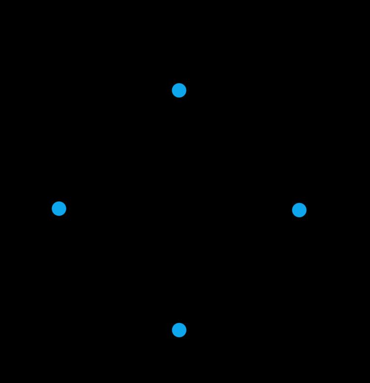
For a QPSK signal, we can take the fourth power:
Two terms (plus a DC component) are produced. An appropriate filter around
Costas loop
Carrier frequency and phase recovery as well as demodulation can be accomplished using a Costas loop of the appropriate order. A Costas loop is a cousin of the PLL that uses coherent quadrature signals to measure phase error. This phase error is used to discipline the loop's oscillator. The quadrature signals, once properly aligned/recovered, also successfully demodulate the signal. Costas loop carrier recovery may be used for any M-ary PSK modulation scheme. One of the Costas Loop's inherent shortcomings is a 360/M degree phase ambiguity present on the demodulated output.
Decision-directed
At the start of the carrier recovery process it is possible to achieve symbol synchronization prior to full carrier recovery because symbol timing can be determined without knowledge of the carrier phase or the carrier's minor frequency variation/offset. In decision directed carrier recovery the output of a symbol decoder is fed to a comparison circuit and the phase difference/error between the decoded symbol and the received signal is used to discipline the local oscillator. Decision directed methods are suited to synchronizing frequency differences that are less than the symbol rate because comparisons are performed on symbols at, or near, the symbol rate. Other frequency recovery methods may be necessary to achieve initial frequency acquisition.
A common form of decision directed carrier recovery begins with quadrature phase correlators producing in-phase and quadrature signals representing a symbol coordinate in the complex plane. This point should correspond to a location in the modulation constellation diagram. The phase error between the received value and nearest/decoded symbol is calculated using arc tangent (or an approximation). However, arc tangent, can only compute a phase correction between 0 and
In low SNR conditions, the symbol decoder will make errors more frequently. Exclusively using the corner symbols in rectangular constellations or giving them more weight versus lower SNR symbols reduces the impact of low SNR decision errors.