
 | ||
Carrier Interferometry (CI) is a spread spectrum scheme commonly used in an Orthogonal Frequency-Division Multiplexing (OFDM) communication system for multiplexing and multiple access, enabling the system to support multiple users at the same time over the same frequency band.
Contents
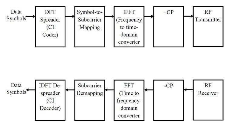
Like MC-CDMA, CI-OFDM spreads each data symbol in the frequency domain. That is, each data symbol is carried over multiple OFDM subcarriers. But unlike MC-CDMA, which uses binary-phase Hadamard codes (code values of 0 or 180 degrees) or binary pseudonoise, CI codes are complex-valued orthogonal codes. In the simplest case, CI code values are coefficients of a discrete Fourier transform (DFT) matrix. Each row or column of the DFT matrix provides an orthogonal CI spreading code which spreads a data symbol. Spreading is achieved by multiplying a vector of data symbols by the DFT matrix to produce a vector of coded data symbols, then each coded data symbol is mapped to an OFDM subcarrier via an input bin of an inverse fast Fourier transform (IFFT). A block of contiguous subcarriers may be selected, or to achieve better frequency diversity, non-contiguous subcarriers distributed over a wide frequency band can be used. A guard interval, such as a cyclic prefix (CP), is added to the baseband CI-OFDM signal before the signal is processed by a radio front-end to convert it to an RF signal, which is then transmitted by an antenna.
A significant advantage of CI-OFDM over other OFDM techniques is that CI spreading shapes the time-domain characteristics of the transmitted waveform. Thus, CI-OFDM signals have a much lower peak-to-average-power ratio (PAPR), or crest factor, compared to other types of OFDM. This greatly improves power efficiency and reduces the cost of power amplifiers used in the radio transmitter.
A CI-OFDM receiver removes the cyclic prefix from a received CI-OFDM transmission and performs OFDM demodulation with a DFT (e.g., an FFT) typically used in OFDM receivers. The CI-spread symbol values are collected from their respective subcarriers in an inverse-mapping process and may be equalized to compensate for multipath fading or processed for spatial demultiplexing. The CI de-spreader performs an inverse-DFT on the spread symbols to recover the original data symbols.
Since CI coding can shape the time-domain characteristics of the transmitted waveform, it can be used to synthesize various waveforms, such as direct-sequence spread spectrum and frequency shift key [4] signals. The advantage is that the receiver can select time-domain or frequency-domain equalization based on how much scattering occurs in the transmission channel. For rich scattering environments, frequency-domain equalization using FFTs requires less computation than conventional time-domain equalization and performs substantially better.
History of CI
CI was introduced by Steve Shattil, a scientist at Idris Communications, in U.S. Pat. No. 5,955,992, filed February 12, 1998, and in the first of many papers in April, 1999. The concept was inspired by optical mode-locking in which frequency-domain synthesis using a resonant cavity produces desired time-domain features in the transmitted optical signal. In radio systems, users share the same subcarriers, but use different orthogonal CI codes to achieve Carrier Interference Multiple Access (CIMA) via spectral interferometry mechanisms.
Many applications of CI principles were published in dozens of subsequent patent filings, conference papers, and journal articles. CI in frequency-hopped OFDM is described in the international patent application WO 9941871. CI in optical fiber communications and MIMO is described in US 7076168. CI coding of reference signals is disclosed in US 6331837 and US 7430257. The use of CI for linear network coding and onion coding is disclosed in US 20080095121 in which random linear codes based on the natural multipath channel are used to encode transmitted signals routed by nodes in a multi-hop peer-to-peer network.
The similarity between antenna array processing and CI processing was recognized since the earliest work in CI. When CI is combined with phased arrays, the continuous phase change between subcarriers causes the array’s beam pattern to scan in space, which achieves transmit diversity and represents an early form of cyclic delay diversity. Combinations of CI coding with MIMO precoding have been studied, and the idea of using CI in MIMO pre-coded distributed antenna systems with central coordination was first disclosed in a provisional patent application in 2001. CI-based software-defined radio (SDR) that implemented four different protocol stacks was developed at Idris in 2000 and described in US 7418043.
Mathematical description
In spread-OFDM, spreading is performed across orthogonal subcarriers to produce a transmit signal expressed by x = F−1Sb where F−1 is an inverse DFT, S is a spread-OFDM code matrix, and b is a data symbol vector. The inverse DFT typically employs an over-sampling factor, so its dimension is KxN (where K > N is the number of time-domain samples per OFDM symbol block), whereas the dimension of the spread-OFDM code matrix is NxN.
At the receiver, the received spread-OFDM signal is expressed by r = HF−1Sb, where H represents a channel matrix. Since the use of a cyclic prefix in OFDM changes the Toeplitz-like channel matrix into a circulant matrix, the received signal is represented by
r = F−1ΛHFF−1Sb
= F−1ΛHSbwhere the relationship H = F−1ΛHF is from the definition of a circulant matrix, and ΛH is a diagonal matrix whose diagonal elements correspond to the first column of the circulant channel matrix H. The receiver employs a DFT (as is typical in OFDM) to produce
y = ΛHSb.
In the trivial case, S = I, where I is the identity matrix, gives regular OFDM without spreading.
The received signal can also be expressed as:
r = F−1ΛHFF−1(ΛCF)b,
where S = ΛCF, and C is a circulant matrix defined by C = F−1ΛCF, where ΛC is the circulant’s diagonal matrix. Thus, the received signal, r, can be written as
r = F−1ΛHΛCFb = F−1ΛCΛHFb,
and the signal y after the receiver's DFT is y = ΛCΛHFb
The spreading matrix S can include a pre-equalization diagonal matrix (e.g., ΛC = ΛH−1 in the case of zero-forcing), or equalization can be performed at the receiver between the DFT (OFDM demodulator) and the inverse-DFT (CI de-spreader).
In the simplest case of CI-OFDM, the spreading matrix is S = F (i.e., ΛC = I, so the CI spreading matrix is just the NxN DFT matrix). Since OFDM’s over-sampled DFT is KxN, with K>N, the basic CI spreading matrix performs like a sinc pulse-shaping filter which maps each data symbol to a cyclically shifted and orthogonally positioned pulse formed from a superposition of OFDM subcarriers. Other versions of CI can produce alternative pulse shapes by selecting different diagonal matrices ΛC.
Useful Properties
- Low PAPR (Crest Factor)
- Low sensitivity to non-linear distortion
- Low sensitivity to carrier-frequency offset
- Robustness to deep fades (spectral nulls)