
 | ||
In data processing systems (computers), a cache memory or memory cache (or sometimes also CPU cache (*)) is a fast and relatively small memory, not visible to the software, that is completely handled by the hardware, that stores the most recently used (MRU) main memory (MM) (or working memory) data.
Contents
- Functional principles of the cache memory
- Cache efficiency
- Cache organization and structure
- Fully associative cache
- Direct mapped cache
- Set associative cache
- Replacement policy
- Instruction and data cache
- Non blocking cache
- Write policy
- Write through
- Write back or copy back
- Write allocate
- Write no allocate
- Cache levels
- Multi level cache hierarchy function
- Inclusive and exclusive cache
- Shared cache
- Multi bank and multi ported cache
- Multi bank cache
- Linear addressing
- Cache interleaving
- Multi ported cache
- Multiple cache copies
- Virtual multi porting cache
- Hybrid solution
- Cache coherency
- Snoopy coherency protocol
- SMP symmetric multiprocessor systems
- Cache states
- Various coherency protocols
- Snoopy coherency operations
- Coherency protocols
- General considerations on the protocols
- Directory based cache coherence message passing
- Remote cache
- cc NUMA cache coherency
- Shared cache coherency protocol
- Multi core systems
- Overview
- Stack cache implementation
- MMU
- TLB
- Virtual addressing
- Coherency problem
- Physical addressing
- Pseudo virtual addressing
- References
The function of the cache memory is to speed up the MM data access (performance increasing) and most important, in multiprocessor systems with shared memory, to reduce the system bus and MM traffic that is one of the major bottleneck of these systems.
Cache memory makes use of the fast technology SRAM (static random-access memory cells), against a slower MM DRAM (dynamic random-access memory), connected directly to the processor(s).
The term "cache" is derived from the French (pronounced /ˈkæʃ/cash/ (deprecated template)) and means "hidden".
This term has many meanings depending on the context. Examples are: disk cache, TLB (translation lookaside buffer) (Page Table cache), branch prediction cache, branch history table, Branch Address Cache, trace cache, that are physical memories. Others are handled by the software, to store temporary data in reserved MM space (again disk cache (page cache), system cache, application cache, database cache, web cache, DNS cache, browser cache, router cache, etc.). Some of these last ones are actually only "buffers" , that is a non-associative memory with sequential access (strings of data) against the random accesses through an associative "memory-to-cache" address of a classic cache.
The term "cache memory" or "memory cache" or shortly "cache" without any specification, usually is referred to a
"hidden memory that stores a subset of main memory content "
and specifically the "Instructions" of a program and the related "Data" that must be processed.
Cache general definition
The Cache is a memory that stores temporary data, in "silent mode" to upper level of utilization,
for a quick reusing.
Functional principles of the cache memory
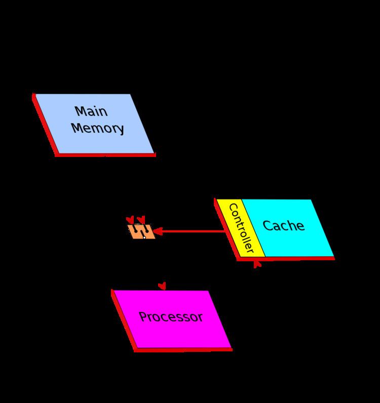
1. In MM read operation, the cache controller first of all checks if the data is stored in cache.
2. In case of match (Hit - cache hit ) the data is fastly and directly supplied from the cache
to the processor without involving the MM.
3. Else (Miss - cache miss ) the data is read from MM.
Cache Memory operation is based on two major "principles of locality" (see Locality of reference):
- Temporal locality - Spatial locality'(Note – for brevity, the term "data" often will be used instead of "cache line" or "cache block")
Cache efficiency
Cache efficiency is measured in terms of "Hit Rate". Hit Rate represents the percentage of Hits (data found in cache) compared to the total number of cache accesses. The opposite of "Hit" is called "Miss"
The cache efficiency depends by several elements: cache size, line size, type and cache architecture (see below) and applications. A good figure of the cache efficiency, for business applications, may be in the range of 80-95 % of hit.
Cache organization and structure
There are three basic structures and two (plus one) types of caches:
Types:
Fully associative cache
Any memory block can be stored in any cache location. It is called "fully associative" because each data stored in cache is associated to its full address.
The cache is divided into two arrays: Directory and Data. The Directory is also divided into two fields: data attribute bits or State and data address ADD (address of memory block).
Data attribute includes the Valid bit and several other flags as Modified bit (M), Shared bit (S) and others (see below Cache states). In addition can include the "protection bits" like "Supervisor/User" and "Write protection".
In fully associative cache the full address of the block is stored. When a data is read from cache, all addresses stored into "Directory" field are simultaneously compared with the MM address block of the required data. If match is found with valid data (hit), the correspondent data is read from the cache. In case of miss, the data block is read from MM. The data read from MM is also then stored in cache that will replace (overwrite) the selected cache line according to Replacement policy.
Fully Associative cache has high efficiency. The data can be stored in any entry, but it is expensive in term of circuits. It requires independent simultaneous ways of access and a comparator for each cache entry. Therefore, usually, the size of this type of cache is very small and used only for specific cases ( e.g. TLB). Generally this cache is never used as cache memory, but instead the direct-mapped and set-associative are used.
Direct mapped cache
In direct mapped (or single set-associative cache) any memory block can be stored in one specific cache entry only. The entry where to store the block is direct derived from the memory address (so that the name "Direct-Mapped").
Cache size is smaller than the MM, therefore the memory address must be reduced to match the cache space. All memory data must take place in a lower space, but of course, not at the same time. Many algorithms, called hash coding or (hashing), are used to do this. The common solution (*) to obtain the cache address is to use directly a part of the memory address, and more precisely, the field called Index, that is, excluding the offset, the Least Significant Bits (LSB) of the address (see fig. Cache addressing). The offset (line offset) is the address field used for the internal cache line addressing at byte-level. For instance having a 32-bit memory addressing (4 GB space), and a 4 MB cache size with 256 B line size, the less significant bits (8-21), the Index, are used to select the entry cache. This linear addressing solution, in Demand-paging Virtual memory (see also below Virtual memory), allows to store a full Memory page in cache.
(*) Note – Another possible hash coding algorithm, but used same time only for TLB, is the "bit XORing" of the address. The address reduction is obtained making an XOR (exclusive OR) between pairs of bits. This method generates a pseudo-random addressing.All data having the same Index, called synonyms, are stored in the same entry, so that only one synonym at a time can take place in cache (synonym conflict). Synonyms differ each other for the MSB (Most Significant Bits) address field.
To distinguish different synonyms, the MSB (named address Tag) is stored in cache directory (in previous example bits (22-31). When a data is read from the cache, the MSB of the directory of the cache is compared with the MSB of the memory address of the data to be read. As well as in Fully Associative, in case of hit, the data is read from cache, else miss, from MM.
The distance between two synonyms, in term of address, is a multiple of the cache size. Synonym conflict decrease with increasing the cache size because the distance between synonyms increase.
In this type of cache only a cache line at a time is selected and therefore only a comparator is needed.
To minimize synonym problem a Set Associative cache is used.
Set associative cache
Set associative cache (or multi-way-direct-mapped) is a combination of two previous approaches and it is used to reduce synonyms conflict.
This cache is composed by a set of identical Direct Mapped cache, addressed in the same identical way, so that for each entry a set of alternative cache line are available to store more than one synonym. Synonyms can be stored in any set of the direct mapped of the selected entries, depending on the (Replacement policy) algorithm used (usually LRU).
Usually the number of ways is in the range of 2-8/16 or more, up to 48 (AMD Athlon) and 128 (IBM POWER3), depending of the type of the cache (Instruction/Data).
In a Set Associative cache there is an address comparator for each set.
Depending on the "Replacement policy" adopted, the Directory may or not contain also the Replacement bits to select the cache line candidate to be replaced.
Replacement policy
(cache line deallocation)
When there are more than one available entry to store a data, as in case of Fully Associative and Set Associative cache, the entry to be replaced is selected by the "Replacement policy" adopted.
There are different policies.
The main are:
Instruction and data cache
Two types of information are stored in MM, Instructions (also called code) and Data (as operands).
Unified cache
Separated cache
There are three advantages in separated caches:
- Interference reduction between two different structures of data.
- Allows "Harvard architecture " implementation. This type of architecture increases the parallelism execution of the processor because allows parallel instructions accesses (prefetching) with the access and execution of the previous data related to the previous instructions (independent parallel access ways).
- No interference, in multiprocessor systems, between snoopy activity and processor activity on the I-Cache. Snoopy activity is generally made only in D-Cache (see below Write policy and Snoopy and processor activity interference).
Non-blocking cache
Most caches can only handle one outstanding request at a time. If a request is made to the cache and there is a miss, the cache must wait the data from the memory, and until then, it is "blocked". A non-blocking (or lock-free) cache has the ability to work on other requests while waiting for memory to supply any misses.
Write policy
The cache's write policy determines how it handles writes to memory locations that are currently being held in cache.
Generally only the Data Cache is involved, because usually instructions are not self-modifying, and in the case of code self-modifying, the software may force the CPU to store this code only in MM without involving the cache (see for instance AMD64 Self-Modifying Code).
There are two basic policy types:
Write through
Write-back (or copy back)
In case of miss on write there are two different solutions:
Write allocate
Write allocate on miss called also Fetch-on-write or RWITM (Read With Intent To Modify) or Read for WriteWrite no-allocate
( or no-Write allocate)
The data is directly written in MM bypassing the cache
Cache levels
In a system more than one cache can be used. The caches are organized in hierarchy levels. Up to 4 level, L1 to L4 or more are possible.
Larger cache have better hit rates but a longer latency. Multi-level cache allows fast access with high hit-rate.
Multi-level cache generally operates by checking the smallest cache first, of lower level, the Level 1 (L1); if hits, the processor proceeds at high speed. If the smaller cache misses, the next larger cache (L2) is checked, and so on for the highest level cache.
Technology improving allows enough space to store a small L1 cache inside the processor chip. An internal cache is faster than an external cache but has lower Hit Rate due to smaller size, typically in the ranges from 8 KB to 64 KB. To increase the global cache size and so the Hit rate, a greater L2 cache closely coupled to the processor is used. Typically L2 size is in the range from 64 KB to 8 MB. L2 can be external or internal to the processor chip or package. In this last case a larger external L3 cache (4-256MB) can be also used. In multi-core systems L3 can be implemented in a MCM (Multi-Chip Module) (e.g. POWER4).
Usually L1 is a Set Associative separated, Instruction and Data cache. L2 cache can be an unified or separated cache as well as can be a Direct Mapped or Set Associative cache. The same for L3 cache.
Multi-level cache hierarchy function
- L1 --> Inside the processor chip. Fast access. - L2 --> To increase the global size and for data coherency. - L3 --> To increase the global size. - L4 --> Remote cache for cc-NUMA Clustering System.Note: The cache line size of the upper level cache can be equal or greater of the lower level cache.
Inclusive and exclusive cache
Cache can be inclusive or exclusive.
Shared cache
Processors can share a common cache. Shared caches generally are used for data coherency in multi-core systems and for cost reduction (see below Shared cache – coherency protocol).
Multi-bank and multi-ported cache
Superscalar processor architecture allows simultaneous parallel instructions execution (taking advantage of the intrinsic parallelism in the instruction stream/multithread ). In these kind of processors there are several function units of the same type, along with additional circuitry to dispatch instructions to the units. Most superscalar designs include more than one arithmetic-logic unit. For instance in IBM POWER3 up to eight instructions, two floating point, two load/store, three fixed point (two single-cycle integer, a multi-cycle integer) and a branch can be in execution in each cycle. Ready instructions are issued out of order from the issue queues, allowing instructions of different types, as well as of the same type, to execute out of order by using the Register renaming technique for synchronization and reorder of the results.
Parallel instructions execution requires multiple simultaneous L1 D-cache accesses. Conflicts occur when two or more requests need to access to the same cache bank simultaneously. This conflict can be partially eliminated by using using multi-bank and/or multi-ported cache techniques.
There are several solutions
Multi-bank cache
L1 D-cache is divided in multiple independently-addressed banks.
There are two approaches:
Linear addressing
The banks are accessed in parallel through a crossbar. The addressing is linear, that is the next address of the last address of a bank is the first address of the next bank. The banks are selected in sequence by using the most significant bits (MSB) of the address Index (for instance, with 8 banks, the three bits 21-19 of above example in Cache addressing). Multiple banks can support multiple requests per cycle when they do not map to the same bank.
Multi-bank approach may be efficient for applications that lack of data locality (statistically independent data), but for applications with good spatial locality, such consecutive reference, simultaneous multiple accesses are not allowed due to a bank conflict (bank collision).
Cache interleaving
Consecutive cache line are placed in consecutive banks. The cache line addressing is interleaved (horizontally distributed) across the banks as shown in the figure on the right. The banks are selected by using the low-order bits of the Index of the address (for instance, with 8-way interleaving, the three bits 10-8 of above example in Cache addressing).
The common number of banks are two, four or eight (e. g. IBM POWER3), named two-way, four-way or eight-way interleaving respectively.
Cache interleaving gives advantages specially in multiple data strings operations. For instance, suppose a two-way interleaved cache with address pairs in Bank 0 and address odd in Bank 1 and two programs (threads) that operate on two independent strings. The fist program can access Bank 0 while the second accesses Bank 1. On next access, the first program can access Bank 1 while the second accesses Bank 0, and so on alternatively. In case of bank collision, that is simultaneous access to the same bank, a program at the beginning must wait just for a step (the first time only), then can start. Like a linear addressing also in multiple simultaneous random accesses there are advantages depending on the banks number. Conflict probability decreases increasing the banks number.
Example of interleaving: IBM POWER3's L1 data cache an eight-way interleaved cache, is capable of two loads, one store, and one cache line reload per cycle.
Multi-ported cache
(or multi-port cache or true multi-porting or ideal multi-porting )
Multiple ports allow multiple parallel accesses to the cache, in the same clock cycle, that operate independently from each other.
Multi-ported caches offer the highest possible access rate per cycle but are complex, and thus slow and costly. Ideal multi-porting implies non-standard cache cell structure. While a regular single-ported static memory cell requires 6 field-effect transistors to be built upon, a dual-ported static memory cell needs additional 2 transistors. Therefore, this solution can only be used for few ports, usually two ports read and one port write (e.g. POWER4).
Multiple cache copies
(mirroring or cloning)
Cache with "n" identical copies (clones) with independent simultaneous addressing. Drawback: cache replicated without benefit to storage space. Moreover, store requests are sent simultaneously to all cache copies, thus no other cache request can be sent in parallel. Since about 30% of memory accesses are stored this solution is severely limited.
Virtual multi-porting cache
(time division multiplexing)
Time division multiplexing is a technique which may be also referenced as cache over-clocking. Cache memory running at 2x (3x, 4x) processor clock speed so that the cache can be accessed two (three, four) time per clock.
Hybrid solution
Combination of cache interleaved with multi-port. Multiple banks interleaved allow parallel access at low cost while multiple ports help removing bank conflicts.
Cache coherency
In systems as SMP – Symmetric Multiprocessor System, multi-core and NUMA system, where a dedicated cache for each processor, core or node is used, a consistency problem may occur when a same data is stored in more than one cache. This problem arises when a data is modified in one cache. This problem can be solved in two ways:
1. Invalidate all the copies on other caches (broadcast-invalidate) 2. Update all the copies on other caches (write-broadcasting), while the memory may be updated (write through) or not updated (write-back).Note: Coherency generally applies only to data (as operands) and not to instructions (see Self-Modifying Code).
The schemes can be classified based on:
– Snoopy scheme vs Directory scheme and vs Shared caches
– Write through vs Write-back (ownership-based) protocol
– Update vs Invalidation protocol
– Intervention vs not Intervention
– Dirty-sharing vs not-dirty-sharing protocol (MOESI vs MESI)
Three approaches are adopted to maintain the coherency of data.
Snoopy coherency protocol
Protocol used in bus-based systems like a SMP systems
SMP – symmetric multiprocessor systems
Systems operating under a single OS (Operating System) with two or more homogeneous processors and
with a centralized shared Main Memory
Each processor have a its own cache that acts as a bridge between processor and Main Memory. The connection is made using a System Bus or a crossbar (xbar) or a mix of two previously approach, bus for address and crossbar for Data (Data crossbar).
The bottleneck of these systems is the traffic and the Memory bandwidth. Bandwidth can be increasing by using large data bus path, data crossbar, memory interleaving (multi-bank parallel access) and out of order data transaction. The traffic can be reduced by using a cache that acts as a "filter" versus the shared memory, that is the cache is an essential element for shared-memory in SMP systems.
In multiprocessor systems with separate caches that share a common memory, a same datum can be stored in more than one cache. A data consistency problem may occur when a data is modified in one cache only.
The protocols to maintain the coherency for multiple processors are called cache-coherency protocols.
Usually in SMP the coherency is based on the "Bus watching" or "Snoopy" (from the dog Snoopy ) approach.
In a snooping system, all the caches monitor (or snoop) the bus transactions to intercept the data and determine if they have a copy on its cache.
Various cache-coherency protocols are used to maintain data coherency between caches.
These protocols are generally classified based only on the cache states (from 3 to 5 and 7 or more) and the transactions between them, but this could create some confusion.
This definition is incomplete because it lacks important and essential information as the actions that these produce. These actions can be invoked from processor or bus (e.g. intervention, invalidation, broadcasting, updating, etc.). The type of actions are implementation depending. Protocols having the same states and the same transaction rules may be different, for instance protocol MESI with shared-intervention on unmodified data and MESI without intervention (see below). Protocols with different states may be practically the same protocol, for instance the 4-state MESI Illinois and 5-state MERSI (R-MESI) IBM / MESIF-Intel protocols are only a different implementation of the same functionality (see below).
The most common and popular protocols are considered the 4-state cache known as acronyms MESI and 5-state MOESI, this just only for easy pronunciation, terms derived from the name of the states used. Other protocols use the same states or un subset of these but with different implementations and often with different but equivalent terminology. With the term MESI or MOESI or a subset of these, generally it is referred to a class of protocols instead of a specific protocol.
Cache states
The states MESI and MOESI are often and more commonly called by different names.
Special states:
Various coherency protocols
Protocols
————————————————————————————————————————
Terminology used
F=Forward – Intel Intel Nehalem
– Note: The main terminologies are SD-D-R-V-I and MOESI and so they will be used both.
————————————————————————————————————————
Mu=Unsolicited Modified – Modified Exclusive – (D/M) (*)
T=Tagged – Modified Owner not Exclusive (SD/O)
Me=Valid Exclusive – (R/E)
S=Shared – (V)
SL=Shared Last – Sourced local – (Shared Owner Local)
I=Invalid – (I)
(*) Special state – Asking for a reservation for load and store doubleword (for 64-bit implementations).
————————————————————————————————————————
Snoopy coherency operations
- Bus Transactions - Data Characteristics - Cache OperationsBus transactions
The main operations are:
- Write Through - Write-Back – Write Allocate – Write-no-Allocate – Cache Intervention – Shared Intervention – Dirty Intervention - Invalidation - Write-broadcast - Intervention-broadcastingData characteristics
There are three characteristics of cached data:
- Validity - Exclusiveness - Ownership(*) – Implementation depending.
Note: Not to confuse the more restrictive "owner" definition in MOESI protocol with this more general definition.
Cache operations
The cache operations are:
- Read Hit - Read Miss - Write Hit - Write MissCoherency protocols
– warning – For simplicity all Read and Write "miss" state transactions that obviously came from I state (or Tag miss), in the diagrams are not depicted. They are depicted directly on the new state. – Note – Many of the following protocols have only historical value. At the present the main protocols used are R-MESI type / MESIF and HRT-ST-MES (MOESI type) or a subset of this.————————————————————————————————————————
MESI protocol
States MESI = D-R-V-I
– Use of a bus "shared line" to detect "shared" copy in the other caches————————————————————————————————————————
MOESI protocol
States MEOSI = D-R-SD-V-I = T-MESI IBM
– Use of bus "shared line" to detect "shared" copy on the other caches————————————————————————————————————————
Illinois protocol
States MESI = D-R-V-I
– Characteristics:————————————————————————————————————————
Write-once (or write-first) protocol
States D-R-V-I (MESI)
– Characteristics:————————————————————————————————————————
Bull HN ISI protocol
(Bull-Honeywell Italia)
States D-SD-R-V-I (MOESI)
Patented protocol (F. Zulian)
————————————————————————————————————————
Synapse protocol
States D-V-I (MSI)
- Characteristics:————————————————————————————————————————
Berkeley protocol
States D-SD-V-I (MOSI)
- Characteristics: - As with MOESI without E state - No use of "shared line"————————————————————————————————————————
Firefly (DEC) protocol
States D-VE-S (MES)
- Characteristics:————————————————————————————————————————
Dragon (Xerox) protocol
States D-SD-VE-SC (MOES)
Note – the state SC, despite of the term "clean", can be "clean" or "dirty" as the S state of the other protocols. SC and S are equivalents
- Characteristics:————————————————————————————————————————
MERSI (IBM) / MESIF (Intel) protocol
States MERSI or R-MESI
States MESIF
Patented protocols – IBM (1997) – Intel (2002)
————————————————————————————————————————
MESI vs MOESI
MESI and MOESI are the most poplar protocols
It is common opinion that MOESI is an extension of MESI protocol and therefore it is more sophisticate and more performant. This is thru only if compared with standard MESI, that is MESI with "not sharing intervention". MESI with "sharing intervention", as MESI Illinois like or the equivalent 5-state protocols MERSI / MESIF , are much more performant than the MOESI protocol.
In MOESI, cache-to-cache operations is made only on modified data. Instead in MESI Illinois type and MERSI / MESIF protocols, the cache-to-cache operations are always performed both with clean that with modified data. In case of modified data, the intervention is made by the "owner" M, but the ownership is not loosed because it is migrated in another cache (R/F cache in MERSI / MESIF or a selected cache as Illinois type). The only difference is that the MM must be updated. But also in MOESI this transaction should be done later in case of replacement, if no other modification occurs meanwhile. However this it is a smaller limit compared to the memory transactions due to the not-intervention, as in case of clean data for MOESI protocol. (see e.g. "Performance evaluation between MOESI (Shanghai) and MESIF Nehalem-EP")
The most advance systems use only R-MESI / MESIF protocol or the more complete RT-MESI, HRT-ST-MESI and POWER4 IBM protocols that are an enhanced merging of MESI and MOESI protocols
Note: Cache-to-cache is an efficient approach in multiprocessor/multicore systems direct connected between them, but less in Remote cache as in NUMA systems where a standard MESI is preferable. Example in POWER4 IBM protocol "shared intervention" is made only "local" and not between remote module.
————————————————————————————————————————
RT-MESI protocol
States RT-MESI
IBM patented protocol
Processor operations
————————————————————————————————————————
RT-ST-MESI protocol
It is an improvement of RT-MESI protocol and it is a subset of HRT-ST-MESI protocol
ST = Shared-Tagged - Use of the "Shared-Tagged" state allows to maintain intervention after deallocation of a Tagged cache lineAn additional improvement can be obtained using more than a ST state, ST1, ST2, … STn.
- In Read Miss, T is changed in ST1 and all the indices of the others STi are increased by "1. - In case of T deallocation, ST1 stops the "Copy Back" transaction, changes its state in T and all the indices of the others STi are decrease by "1". - In case of a deallocation, for instance STk, the chain will be interrupted and all the STi with index greater of "k" are automatically loosen in term of ST and will be considered de facto only as simple S states also if they are set as ST. All this because only ST1 intervenes to block and to replace itself with T. For instance if we have a situation type T, ST1, ST3, ST4 with ST2 replaced, if T will be replaced the new situation will be T, ST2, ST3 without any ST1.————————————————————————————————————————
HRT-ST-MESI protocol
IBM patented full HRT-ST-MESI protocol
- I state = Invalid Tag (*) – Invalid Data
- H state = Valid Tag – Invalid Data
- I state is set at the cache initialization and its state changes only after a processor Read or Write miss. After it will not return more in this state.
- H has the same functionality of I state but in addition with the ability to capture any bus transaction that match the Tag of the directory and to update the data cache.
- After the first utilization I is replaced by H in its functions
- The main features are :(*) – Note: The Tag for definition is always valid, but until the first updating of the cache line it is considered invalid in order to avoid to update the cache also when this line has been not still required and used.
————————————————————————————————————————
POWER4 IBM protocol
States M-T-Me-S-I -Mu-SL = RT-MESI+Mu
- Use of the "shared line" - Used in multi-core/module systems – multi L2 cache - This protocol is equivalent to the RT-MESI protocol for system with multi L2 cache on multi-module systems————————————————————————————————————————
General considerations on the protocols
Under some conditions the most efficient and complete protocol turns out to be the HRT-ST-MESI protocol.
- Write Back - Intervention both with dirty than shared-clean data - Reserve states of the Tagged state (Shared-Tagged) - Invalid H (Hover) state auto-updatingSnoopy activity requires to access to the cache directory and may be in conflict with the concurrent processor accesses. This interference increases cache latency.
To reduce or eliminate this interference three solution can be used:
Directory-based cache coherence – message-passing
It is known that the SMP system is limited in scalability. Memory multi-banking and data crossbar allow memory parallel accesses. Use of large caches reduces system bus traffic but not the write invalidate or write broadcast. The main drawback is that all the memory addresses must be snooped using a single bus. To overcome this limitation, a new architecture called "cc-NUMA " is adopted.
cc-NUMA system is a cluster of SMP systems, called "NODEs", connected via a connection network that can be a link that can be a single or double-reverse ring, or multi-ring, point-to-point connections or a mix of these (e.g. IBM Power Systems), bus interconnection (e.g. NUMAq), crossbar, segmented bus (NUMA Bull HN ISI ex Honeywell), Mesh router, etc..
Examples of interconnections:
The main characteristic of cc-NUMA system is to have an unique shared global memory distributed in each node
directly accessed from all the processors of all the nodes
In a NUMA system, the access from a processor to a remote memory of a remote node, is slower compared to the access to its local memory. For this reason this system is called NUMA (Non Uniform Memory Access).
NUMA is also called Distributed Shared Memory (DSM) architecture.
Each node usually is a SMP system, where a processor can be a single processor or a multi-core processor or mix of this two or any other kind of architecture. The fig. aside is just an example.
The difference in access time from local and remote can be also of an order of magnitude, depending on the kind of the connection network used (faster in segmented bus, crossbar and point-to-point interconnection, slower in serial rings connection).
Remote cache
Terminology:
(from a node point view)
To reduce the difference in access time from local and remote data, a Remote cache can be used. This cache stores data read from the other remote memories. Usually this cache is a shared inclusive cache with MESI protocol. L1-L3 caches can be extended MESI type (e.g. R-MESI, RT-MESI, etc.). Each remote data that is stored in local L1-L3 caches, is stored also in this cache (for inclusivity). This cache is the 4th level for the remote data only (cache of remote memories), while L1-L3 caches can stored instead local and remote data (cache of the node related to the global memory). From a node internal point of view this cache can see as an extension of the local memory (remote data stored locally).
Because the function of this cache is to reduce the remote access time at least as the own local memory access time, an hybrid technology may be used – SRAM for directory, DRAM for data cache. This solution allows to implement a large cache as required from these systems.
The Remote cache can store both instructions (code) and data (as operands), but usually only the data is stored. The access to private data, such as code and the stack, often can be performed locally by copying the code (code replication) from another node (increasing efficiency).
cc-NUMA cache coherency
Cache coherency in NUMA system (cc-NUMA) is obtained by using a Directory-based – Message-passing protocol. This approach was proposed for the first time by Censier and Feaultrier and described also in "The Directory-Based Cache Coherency Protocol for DASH Multiprocessor ".
Since usually not all the nodes are access at the same time on the same data, the coherence control can be done much more effectively if this is made in selective mode only on the involved nodes.
Cache coherency at system level (inter-node) is therefore maintained by a directory-based protocol using a directory associated to each local memory that keeps track of the global state of all memory blocks of its local memory, and an indicator (node "indicator bit") in order to indicate which node has the memory blocks cached in its remote cache. Coherency inside the node, instead, is based on the bus-snoopy scheme.
Each directory entry has N-1 node indicator bit and three global states associated with each memory block that are a copy of all the remote caches states.
* The remote cache stores data read from the remote memories of other nodes.
* The local memory directory holds trace of the local data and their state, read from the local memory,
that are stored in remote caches of the other nodes.
- Warning – not to be confused the "local memory directory" with the "directory of the remote cache". The first contains information on the local data, the second on the remote data
The are four possible situations for a node:
Local memory read
- A local memory read transaction from a processor of a same node is snooped and handled in same way like with a normal SMP system. - L3 missLocal memory write
- Hit Shared in L3 - Hit Esclusive in L3 - Miss - As with a "local memory read miss" with a command of "Invalidate" (RWITM), then as with a "write hit Exclusive"Remote memory read
- MissRemote memory write
- Hit "Exclusive" in L3 - Hit "Shared" in L3 - MissShared cache – coherency protocol
Typically used in Multi-core systems for coherency and cost reduction (space save).
Multi-core systems
(core = integrated processor)
Multi-core system, called chip multiprocessors, multicore chips, and many-core chips, is a special kind of multiprocessor where all processors are on the same chip (MCM – Multi-Chip Module)
Multi-core processors are MIMD systems: different cores execute different threads (Multithread/Multiple Instructions – parallel execution on the same Context (computing) of small sequence of programmed instructions), operating on different parts of memory (Multiple Data).
A common solution of Multi-core systems implementation make use of multi-level inclusive shared cache to maintain data coherency.
Inclusivity force data to be coherence. Data stored in L1 are stored also in L2 (and in L3 if used). Any L1 changing must be reported in L2 cache and also in L3. If L2 is update or invalidate also all L1 must invalidated or updated (same relation between L2-L3).
Cache coherency is maintained by using a centralized cache controller on shared cache. Shared cache can be L2, or L3 if L2 is a private cache.
The coherency protocol is based on the point-to-point message-passing protocol type as described in cc-NUMA system. The difference is only in directory that in cc-NUMA system is related to the memory and not to the shared cache.
There are two kinds of implementation. Message broadcasting to all or only to the specific L1 cache that stores the data. In the first case the cache coherency protocol is a snoopy-type cache coherency. The shared cache acts as bridge, in substitution of the system bus, forwarding the transaction to all L1 caches for snooping, only if needed, that is when the data is not exclusive in shared cache. In the second case, in directory of the shared cache there is a "indicator bit" for each L1 cache to remember which L1 may have the data (Intel Nehalem).
cc-NUMA in multi-core systems
Multi-core systems can be connected together to form a NUMA system. The coherency is guaranteed through a message-passing between the several L3 shared-caches of the several nodes (see for instance Intel Nehalem, AMD Opteron, MCM Interconnections Power5 IBM, etc..
Overview
In a processor there are some very fast small memories called registers, handled by the software, to store temporary data.
In structured software, is frequent the use of some software routines called procedures to performs a specific task, subroutine or function. Also these procedures may be nested to any level, that is these subroutines in turn can call the other procedures or functions. These procedures make use of the same internal registers in independent mode from to the calling program. Therefore, before to make a Call (procedure call ), it is needed to save these registers and parameters (local variables, return address point, etc.) used by the calling program, informations that will be recovered when returned to the calling program. These information are stored, by the software in memory in dedicate area of the process segment. This area is called Stack. A stack is always a push-down list, meaning that as new requests come in, they push down the old ones related to the Stack Pointer. Actually the list is fixed and it is the stack pointer that moves, up in save operation, down in restore operation. Another way of looking at a push-down list, or stack, is that the program always takes its next item to handle from the top of the stack (LIFO = Last In – First Out). The name Stack is borrowed from the name of the vertical dishes container, with a spring on the bottom, used at the beginning of the 20th century in the old London restaurants, with a spring on the button so that it was the bottom that was lowered or raised, putting or removing the dishes, while the last dishes was always fixed in the top.
To speed up the Call/Return operations, some processors make use of the ''Register windows (sPARC, AMD 29000, Intel i960). In these systems a set of registers (windows) is reserved for each Call (from 2 to up 32 windows). In these systems it is not needed therefore to save any registers, so that the Call and Return operations are very fast, change only the set registers selection.
Stack cache implementation
An alternative solution is the Stack Cache.
Data cache suffers, in general, from a limited hit rate (in the range of 80-90 % for business applications) caused by a non-homogeneous and random data. Significant increase in performance is achieved by using separated data caches for normal data and for stack data.
A stack cache (S-Cache) is intended to maintain a separated cache from L1 data cache (D-cache)
that is accessed in predictable stack-like fashion.
Due to serial characteristics of the stack data, a stack cache can be indexed as a contiguous buffer of memory, which means it can be implemented as a direct-mapped cache.
The stack cache prevents the data stack to be replaced by the normal data. In this way the stack cache can be reach a hit rate near to 100%.
An optimization can be obtained by using a L1 Set Associative cache and reserving one of a set cache for the data stack data (Honeywell Bull Systems). This set is not exclusive reserved for the stack data, but the variable free area not used by the stack data, can be used for the normal data. This means that this set is used for the normal data as in usual mode but with the only restriction that the normal data cannot replace the stack data.
MMU
MMU (Memory Management Unit) is the unit to manage the MM accesses. The main functions are:
- Translation of address from virtual to physical
- Management of TLB miss
- Accesses permission checking of the cache line and of the MM:
TLB
The Virtual memory is the space seen from a process. Generally this space is much greater than the physical memory. This space is segmented in pages of a prefixed size. The Page table (generally loaded in memory) keeps track of where the virtual pages are loaded in the physical memory. The TLB (Translation Lookaside Buffer or "Page Table Cache" or also "Page-Translation Cache") is a cache of the Page table (PTE), that is only a subset of its content is stored in the TLB. The TLB, like with the cache memory, may be '"separated" Instructions (ITLB) and Data (DTLB) or "unified", as well as may be Direct Mapped or Set Associative or Fully Associative. Generally the organization follows the same organization of the associated cache memory, but may be organized in independent ways from this (see TLB). Like with cache, to increase the efficiency it can be used a TLB dual-level by adding an L2 TLB (e.g. Intel Nehalem).
The cache can be addressed in physical or virtual mode. There are pros and cons for both implementations, but normally the physical addressing is that commonly used.
Virtual addressing
In fig. "Virtual Space Address Structure" it is shown an example of virtual address with 4 GB virtual space, 4 MB cache, 4 KB page size and 256 B cache line size.
Virtual or Logical Space is divided in pages. MSB + PA form the page address of virtual space VPA (Virtual Page Address). Also the cache is divided in pages.
The cache stores a subset of the virtual space pages. It is addressed by the Index that is formed by PA + PA Offset, where PA (Page Address) is the page address of the cache and PA Offset is the address of the cache line of a page, while Offset is the address at the byte level of a cache line.
In virtual or logical addressing, a cache is directly addressed by using the Index without having to convert before the address from virtual to physical. Also the TAGs are virtual (logical MSB). This type of addressing is known as Virtual Index – Virtual TAG – VIVT.
In a multiprocessing environment, several different logical addresses of different contexts or processes may refer to the same physical address, or the same logical address of a process may maps several different physical addresses, causing a coherency problem, while on the contrary, within the same context, the same logical address is always related to the same physical address.
There are three possible solutions:
Coherency problem
Because different logical addresses of different contexts may refer to the same physical address (data sharing), more than one cache location may be store the same data, causing a coherency problem in case of write. Only one location would be updated.
There are two main solutions
1 – Synonym prevention - Software prevent or avoid synonyms 2 – Dynamic synonym detectionIn any case the cache must be always flushed when the virtual-to-physical mapping is changed (for instace in case of page replacement).
Physical addressing
In physical addressing, first the TLB (*) is addressed by using the virtual address L.MSB + LPA, then the physical address (PPA) obtained from the TLB (plus PPA Offset) is used to address the cache. Only the part of Virtual address that differs from the Physical address is translate, that is the L.MSB and the LPA.
The TLB is a cache of the Page table and is handled as a normal cache with in addition that the CTX associates to the logical address is compared with CTX stored in TLB because changing context changes also the association LPA-PPA (see virtual addressing).
This solution (Physical Index – Physical TAG – PIPT addressing) is much simpler and avoid any aliasing problem but it is slower because first requires access to the TLB.
(*) – At the beginning the cache size used was small and equal to the page size, therefore the virtual and physical "index" were coinciding and the TLB was accessed in parallel (so that the name "look aside") only to check the physical MSBs, as in virtual addressing.
Pseudo-virtual addressing
- Solution used in Honeywell Bull Italia systems – F. Zulian – US Patent N. 5.165.028This solution gives to all the advantages of both the previous solutions.
* This approach is based on the spatial locality principle.
Referring to the fig. Virtual Space Address Structure, the address virtual/logical "Index" is divided in two parts: Logical Page Address (LPA) (or Page number) and Page Offset (cache line address within the page). The Offset is the address (at byte level) within the cache line.
The Virtual and the Physical Page Offset coincide (as well as, of course, the Offset ). Virtual and Physical address differ for the L.MSB and for the LPA. The TLB translates the logical L.MSB and Logical Page Address (LPA), respectively in physical P.MSB and in Physical Page Address (PPA). PPA + LPA Offset form the physical Index that is used to address the cache.
Spatial locality means that if a access is made in a page there is a high probability that next access is made in the same.Separately for Instructions, Data and for Stack data (if the Stack is used), the probability that the next access is in same page of a previous access is very high due to a very large spatial locality (4 KB or more compared, for instance, to a more small cache line size).
The previous Logical Page address (LPA) with its Context Number (CTX) and the correspondent Page Physical Address (PPA) are stored dedicated registers.
On the next access, the new Logical Page address (LPA) with its Context Number (CTX) is compared with the previous LPA. If match (hit) the correspondent Page Physical address (PPA) register is used to directly address the cache, without the necessity to access to TLB, as like it happens in case of virtual addressing (from which the name Pseudo Virtual addressing).
In case of miss, the PPA is supplied from the TLB, like with the physical addressing without any penalty regarding this last one.
This approach is effective if a "LPA-PPA" set registers is reserved for each type of function: one for instruction address, two for data operands (each instruction can have up to two operand addresses) and eventually one for data stack. Moreover, to increase the efficiency in multithreading systems, a group of dedicated "LPA-PPA" registers can be used one for each thread.
Note – These registers can be see as a L1 cache of TLB, with only one entry, separated for each type of data (instructions, data 1, data 2, stack) and for each thread, that is a L1 TLB cache made by registers therefore very high speed.
With this solution, practically without added cost, in almost all the cases, and particularly for instructions and sequential data strings, the addressing is performed in physical mode but without need to wait for the address translation virtual-to-physical, such like in virtual addressing, but without need to flush the cache in case of page replacement, as required in virtual addressing, and without any coherency problem.