
 | ||
Pocket milling has been regarded as one of the most widely used operations in machining. It is extensively used in aerospace and shipyard industries. In pocket milling the material inside an arbitrarily closed boundary on a flat surface of a work piece is removed to a fixed depth. Generally flat bottom end mills are used for pocket milling. Firstly roughing operation is done to remove the bulk of material and then the pocket is finished by a finish end mill. Most of the industrial milling operations can be taken care of by 2.5 axis CNC milling. This type of path control can machine up to 80% of all mechanical parts. Since the importance of pocket milling is very relevant, therefore effective pocketing approaches can result in reduction in machining time and cost. NC pocket milling can be carried out mainly by two tool paths, viz. linear and non-linear.
Contents
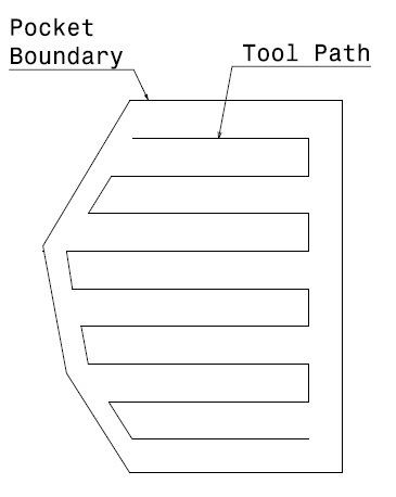
Linear tool path
In this approach, the tool movement is unidirectional. Zig-zag and zig tool paths are the examples of linear tool path.
Zig-zag tool path
In zig-zag milling, material is removed both in forward and backward paths. In this case, cutting is done both with and against the rotation of the spindle. This reduces the machining time but increases machine chatter and tool wear.
Zig tool path
In zig milling, the tool moves only in one direction. The tool has to be lifted and retracted after each cut, due to which machining time increases. However, in case of zig milling surface quality is better.
Non-linear tool path
In this approach, tool movement is multi-directional. One example of non-linear tool path is contour-parallel tool path.
Contour-parallel tool path
In this approach, the required pocket boundary is used to derive the tool path. In this case the cutter is always in contact with the work material. Hence the idle time spent in positioning and retracting the tool is avoided. For large-scale material removal, contour-parallel tool path is widely used because it can be consistently used with up-cut or down-cut method during the entire process. There are three different approaches that fall into the category of contour-parallel tool path generation. They are:
Pair-wise intersection approach
In pair-wise intersection approach, the boundary of the pocket is brought inwards in steps, The offset segments will intersect at concave corners. To obtain the required contour, these intersections are to be trimmed off. On the other hand, in case of convex corner, the offset segments are extended and thereby connected to make the contour. These operations viz. offsetting, trimming and extending are repeatedly done to cover the entire machining volume with sufficient layer of profiles.
Voronoi diagram approach
In voronoi diagram approach, the pocket boundary is segmented and vornoi diagram is constructed for the entire pocket boundary. These vornoi diagrams are used for generating the tool path for machining. This method is considered to be more efficient and robust. Moreover, it avoids topological problems associated with traditional offsetting algorithms.
Curvilinear tool path
In this approach, the tool travels along a gradually evolving spiral path. The spiral starts at the center of the pocket to be machined and the tool gradually moves towards the pocket boundary. The direction of the tool path changes progressively and local acceleration and deceleration of the tool are minimized. Therefore, the tool wear reduces.