 | ||
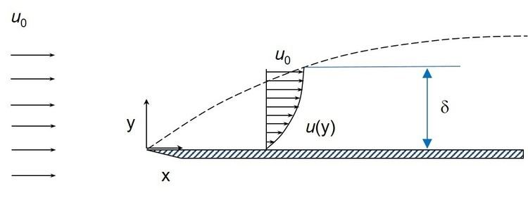
This page describes some parameters used to measure the properties of boundary layers. Consider a stationary body with a fluid flowing around it, like the semi-infinite flat plate with air flowing over the top of the plate (assume the flow and the plate extends to infinity in the positive/negative direction perpendicular to the
Contents
99% Boundary Layer thickness
The boundary layer thickness, δ, is the distance across a boundary layer from the wall to a point where the flow velocity has essentially reached the 'free stream' velocity,
at a point on the wall
For turbulent boundary layers over a flat plate, the boundary layer thickness is given by:
where
The turbulent boundary layer thickness formula assumes 1) the flow is turbulent right from the start of the boundary layer and 2) the turbulent boundary layer behaves in a geometrically similar manner (i.e. the velocity profiles are geometrically similar along the flow in the x-direction, differing only by stretching factors in
The velocity thickness can also be referred to as the Soole ratio, although the gradient of the thickness over distance would be adversely proportional to that of velocity thickness.
Displacement thickness
The displacement thickness, δ* or δ1 is the distance by which a surface would have to be moved in the direction perpendicular to its normal vector away from the reference plane in an inviscid fluid stream of velocity
In practical aerodynamics, the displacement thickness essentially modifies the shape of a body immersed in a fluid to allow an inviscid solution. It is commonly used in aerodynamics to overcome the difficulty inherent in the fact that the fluid velocity in the boundary layer approaches asymptotically to the free stream value as distance from the wall increases at any given location.
The definition of the displacement thickness for compressible flow is based on mass flow rate:
The definition for incompressible flow can be based on volumetric flow rate, as the density is constant:
where
For turbulent boundary layer calculations, the time averaged density and velocity at the edge of the boundary layer must be used. In the equations above,
The displacement thickness is used to calculate the boundary layer's shape factor.
Momentum thickness
The momentum thickness, θ or δ2, is the distance by which a surface would have to be moved parallel to itself towards the reference plane in an inviscid fluid stream of velocity
The definition of the momentum thickness for compressible flow is based on mass flow rate:
The definition for incompressible flow can be based on volumetric flow rate, as the density is constant:
Where
For turbulent boundary layer calculations, the time averaged density and velocity at the edge of the boundary layer must be used. In the equations above,
For a flat plate at zero angle of attack with a laminar boundary layer, the Blasius solution gives.
The influence of fluid viscosity creates a wall shear stress,
Other length scales describing viscous boundary layers include the energy thickness,
Shape factor
A shape factor is used in boundary layer flow to determine the nature of the flow.
where H is the shape factor,
Conventionally, H = 2.59 (Blasius boundary layer) is typical of laminar flows, while H = 1.3 - 1.4 is typical of turbulent flows.
Moment Method
A relatively new method for describing the thickness and shape of the boundary layer utilizes the moment method commonly used to describe a random variable's probability distribution. The moment method was developed from the observation that the plot of the second derivative of the Blasius boundary layer for laminar flow over a plate looks very much like a Gaussian distribution curve. It is straightforward to cast the properly scaled velocity profile and its first two derivatives into suitable integral kernels.
The velocity profiles central moments are defined as:
where the mean location is given by:
There are some advantages to also include descriptions of moments of the boundary layer profile derivatives with respect to the height above the wall. Consider the first derivative velocity profile central moments given by:
where the mean location is the displacement thickness
Finally the second derivative velocity profile central moments are given by:
where the mean location is given by:
With the moments and the mean locations defined, the boundary layer thickness and shape can be described in terms of the boundary layer widths (variance), skewnesses, and excesses (excess kurtosis). Experimentally, it is found that the turbulent boundary layer thickness defined as
Taking a cue from the boundary layer momentum balance equations, the second derivative boundary layer moments,
Calculation of the derivative moments without the need to take derivatives is simplified by using integration by parts to reduce the moments to simply integrals based on the displacement thickness kernel:
This means that the first derivative skewness, for example, can be calculated as:
This parameter was shown to track the boundary layer shape changes that accompany the laminar to turbulent boundary layer transition.
