
 | ||
After about 1910 Baker valve gear was the main competitor to Walschaerts valve gear for steam locomotives in the United States. Strictly speaking it was not a valve gear but a variable expansion mechanism adapted to the Walschaerts layout replacing the expansion link and sliding die block. The Baker arrangement used more pivot bearings or pin joints, but avoided the die slip inherent to the expansion link, with the aim of lessening wear and the need for service; it could also facilitate longer valve travel.
Contents
History
In the early 1900s there were many efforts to create a new valve gear to replace the by-then-standard Walschaerts valve gear. In the United States the Young, Southern, Caprotti and Franklin patterns were used on a few classes, but only the Baker pattern won more than limited acceptance.
The design originated in the A.D. Baker Company, of Swanton, Ohio; a builder of steam traction engines. The idea came from an employee called Gifford but was developed by the Baker company with the first patents being issued in 1903.
The Baker Locomotive Valve Gear was produced by the Pilliod Co. of Swanton, Ohio. Subsequent versions were produced up to the end of steam service. It was particularly popular on the Norfolk and Western Railway, and almost all later N&W engines used it (notably NW 611). Other extensive users included the Chesapeake and Ohio Railroad and the Nickel Plate Road. The New York Central Railroad and the Baltimore and Ohio Railroad also had large classes which used Baker gear. There was always debate about the advantages of Baker gear, the main criticism being the number of pin joints and possible lost motion. Western United States and British railroads tended to continue with the Walschaerts pattern, as did the Pennsylvania Railroad. In Britain Baker gear was popular amongst model engineers but in full-size practice the length of the yoke and the width of the assembly may have been difficult to accommodate within the restricted loading gauge.
Other locomotives to use Baker valve gear were the New Zealand Railways J class, Ja class, Jb class, some Ka class, and the South Australian Railways 620 class.
Operation
The Baker valve gear replaces the expansion link of the Walschaerts gear with an assembly of levers and links which produces the same effect of allowing continuous variation valve travel. The remainder of the gear is the same, so that the return crank and combination lever take the same form, although the proportions are usually modified. The Pilliod Co. sold the gear as a single assembly which was mounted on the frame in the location ordinarily occupied by the Walschaerts expansion link.
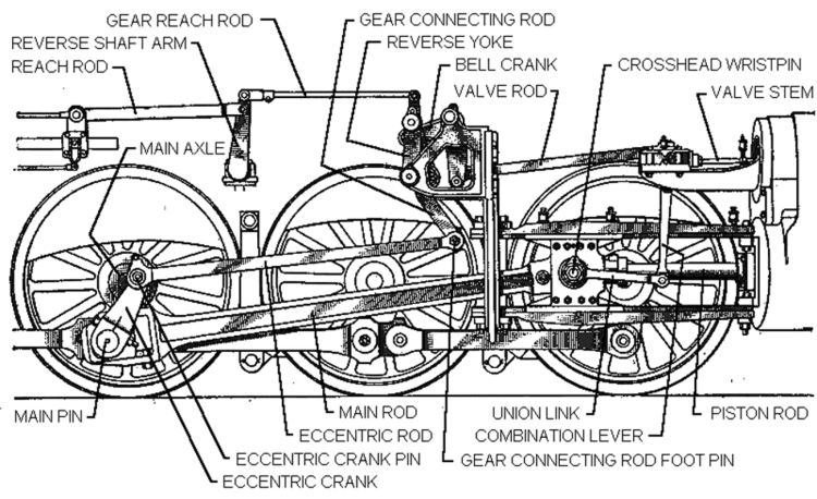
The Baker mechanism consisted of the following parts:
The parts were arranged so that when the yoke was centered, the connection of the main link to the bellcrank was in a line with the two pivots on the yoke. At this point, the back and forth motion of the lower end of the main link left the top relatively motionless as main link swung back and forth on the swing links.
In forward motion, the yoke was pushed forward, so that its upper pivot was in front of the bell crank-main link connection. Moving the eccentric arm back and forth lowered and raised the top of the main link. This motion was translated by the bellcrank into back and forth motion of the radius rod. The angle of the yoke controlled the relative motion, and therefore the cutoff; tilting the yoke backwards reversed the motion of the radius rod.