
 | ||
An aluminum electrolytic capacitor, usually simply called an electrolytic capacitor (e-cap), is a capacitor whose anode (+) consists of pure aluminum foil with an etched surface, covered with a uniformly very thin barrier layer of insulating aluminium oxide, which operates as a dielectric. The electrolyte, which covers the rough surface of the oxide layer, operates as the second electrode, the cathode (-). E-caps have the largest capacitance values per unit volume compared to the two other main conventional capacitor families, ceramic and plastic film capacitors, but much smaller capacitance than similar sized supercapacitors.
Contents
- Oxide layer
- Construction of non solid aluminum electrolytic capacitors
- Comparison of non solid and solid types
- Anode
- Cathode
- Electrolyte
- Separator
- Encapsulation
- Sealing
- Production
- Styles
- History
- Electrical parameters
- Capacitance standard values and tolerances
- Rated and category voltage
- Surge voltage
- Transient voltage
- Reverse voltage
- Impedance
- ESR and dissipation factor tan
- Ripple current
- Chargedischarge stability
- Current surge peak or pulse current
- Leakage current
- Dielectric absorption soakage
- Reliability failure rate
- Lifetime service life
- Failure modes
- Capacitor behavior after storage or disuse
- Parallel connection
- Series connection
- Imprinted markings
- Polarity marking
- Standardization
- Applications
- Advantages and disadvantages
- Market
- References
Aluminum electrolytic capacitors are divided into three subfamilies by the type of electrolyte:
Aluminum electrolytic capacitors with non-solid electrolyte are the most inexpensive type and also those with widest range of sizes, capacitance and voltage values. They are made with capacitance values from 0.1 µF up to 2,700,000 µF (2.7 F), and rated voltages values from 4 V up to 630 V. The liquid electrolyte provides oxygen for re-forming or self-healing of the dielectric oxide layer. However, it can evaporate through a temperature-dependent drying-out process, which causes electrical parameters to drift, limiting the service life time of the capacitors.
Due to their relatively high capacitance values aluminum electrolytic capacitors have low impedance values even at lower frequencies like mains frequency. They are typically used in power supplies, switched-mode power supplies and DC-DC converters for smoothing and buffering rectified DC voltages in many electronic devices as well as in industrial power supplies and frequency converters as DC link capacitors for drives, inverters for photovoltaic, and converters in wind power plants. Special types are used for energy storage, for example in photoflash or strobe applications or for frequency coupling in audio applications.
Aluminum electrolytic capacitors are polarized capacitors because of their anodization principle. They can only be operated with DC voltage applied with the correct polarity. Operating the capacitor with wrong polarity or with AC voltage leads to a short circuit and can destroy the component. The exceptions is the bipolar aluminum electrolytic capacitor, which has a back-to-back configuration of two anodes in one case and can be used in AC applications.
Oxide layer
Electrolytic capacitors use a chemical feature of some special metals, earlier called "valve metals". Applying a positive voltage to the anode material in an electrolytic bath forms an insulating oxide layer with a thickness corresponding to the applied voltage. This oxide layer acts as the dielectric in an electrolytic capacitor. The properties of this aluminum oxide layer compared with tantalum pentoxide dielectric layer are given in the following table:
After forming a dielectric oxide on the rough anode structures, a counter-electrode has to match the rough insulating oxide surface. This is provided by the electrolyte, which acts as the cathode electrode of an electrolytic capacitor. Electrolytes may be "non-solid" (wet, liquid) or "solid". Non-solid electrolytes, as a liquid medium that has an ion conductivity caused by moving ions, are relatively insensitive to voltage spikes or current surges. Solid electrolytes have an electron conductivity, which makes solid electrolytic capacitors sensitive to voltages spikes or current surges. The anodic generated insulating oxide layer is destroyed if the polarity of the applied voltage changes.
Every electrolytic capacitor in principle forms a "plate capacitor" whose capacitance is greater the larger the electrode area A and the permittivity ε, and the thinner the thickness (d) of the dielectric.
The capacitance is proportional to the product of the area of one plate multiplied with the permittivity, divided by the thickness of the dielectric.
The dielectric thickness of electrolytic capacitors is very thin, in the range of nanometers per volt. Otherwise, the voltage strengths of these oxide layers are quite high. With this very thin dielectric oxide layer combined with a sufficiently high dielectric strength the electrolytic capacitors can achieve a high volumetric capacitance. This is one reason for the high capacitance values of electrolytic capacitors compared to conventional capacitors.
All etched or sintered anodes have a much higher surface compared to a smooth surface of the same area or the same volume. That increases the later capacitance value, depending on the rated voltage, by a factor of up to 200 for aluminum electrolytic capacitors. The large surface area compared to a smooth surface is the second reason for the relatively high capacitance values of electrolytic capacitors compared to other capacitor families.
All electrolytic capacitors have one special advantage. Because the forming voltage defines the oxide layer thickness, the voltage proof of the later electrolytic capacitor can be produced very simply for the desired rated value, the so-called "CV-Volume". That makes electrolytic capacitors suitable for uses down to 2 V applications in which other capacitor technologies must adhere to much higher limits.
Construction of non-solid aluminum electrolytic capacitors
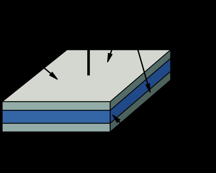
An aluminum electrolytic capacitor with a non-solid electrolyte always consists of two aluminum foils separated mechanically by a spacer, mostly paper, which is saturated with a liquid or gel-like electrolyte. One of the aluminum foils, the anode, is etched (roughened) to increase the surface and oxidized (formed). The second aluminum foil, called the "cathode foil", serves to make electrical contact with the electrolyte. A paper spacer mechanically separates the foils to avoid direct metallic contact. Both foils and the spacer are wound and the winding is impregnated with liquid electrolyte. The electrolyte, which serves as cathode of the capacitor, covers the etched rough structure of the oxide layer on the anode perfectly and makes the increased anode surface effectual. After impregnation the impregnated winding is mounted in an aluminum case and sealed.
By design, a non-solid aluminum electrolytic capacitor has a second aluminum foil, the so-called cathode foil, for contacting the electrolyte. This structure of an aluminum electrolytic capacitor results in a characteristic result because the second aluminum (cathode) foil is also covered with an insulating oxide layer naturally formed by air. Therefore, the construction of the electrolytic capacitor consists of two single series-connected capacitors with capacitance CA of the anode and capacitance CK of the cathode. The total capacitance of the capacitor Ce-cap is thus obtained from the formula of the series connection of two capacitors:
It follows that the total capacitance of the capacitor Ce-cap is mainly determined by the anode capacitance CA when the cathode capacitance CK is very large compared with the anode capacitance CA. This requirement is given when the cathode capacitance CK is approximately 10 times higher than the anode capacitance CA. This can be easily achieved because the natural oxide layer on a cathode surface has a voltage proof of approximately 1.5 V and is therefore very thin.
Comparison of non-solid and solid types
Although the present article only refers in essence to aluminum electrolytic capacitors with non-solid electrolyte, an overview of the different types of aluminum electrolytic capacitors is given here in order to highlight the differences. Aluminum electrolytic capacitors are divided into two sub-types depending on whether they make use of liquid or solid electrolyte systems. Because the different electrolyte systems can be constructed with a variety of different materials, they include further sub-types.
Description of the materials
The following table shows an overview over the main characteristics of the different types of aluminum electrolytic capacitors.
1) Values for a typical capacitor with 100 µF/10–16 V
Aluminum electrolytic capacitors with non-solid electrolyte are the best known and most widely used electrolytic capacitors. These components can be found on almost all boards of electronic equipment. They are characterized by particularly inexpensive and easy to process base materials.
Aluminum capacitors with liquid electrolytes based on borax or organic solvents have a large range of types and ratings. Capacitors with water-based electrolytes are often found in digital devices for mass production. Types with solid manganese dioxide electrolyte have served in the past as a "tantalum replacement". Polymer aluminum electrolytic capacitors with solid conductive polymer electrolytes are becoming increasingly important, especially in devices with a flat design, such as tablet PCs and flat panel displays. Electrolytic capacitors with hybrid electrolytes are relatively new on the market. With their hybrid electrolyte system they combine the improved conductivity of the polymer with the advantage of liquid electrolytes for better self-healing property of the oxide layer, so that the capacitors have the advantages of both low ESR and low leakage current.
Anode
The basic material of the anode for aluminum electrolytic capacitors is a foil with a thickness of ~ 20–100 µm made of aluminum with a high purity of at least 99.99%. This is etched (roughened) in an electrochemical process to increase the effective electrode surface. By etching the surface of the anode, depending on the required rated voltage, the surface area can be increased by a factor of approximately 200 with respect to a smooth surface.
After etching the aluminum anode the roughed surface is "anodic oxidized" or "formed". An electrically insulating oxide layer Al2O3 is thereby formed on the aluminum surface by application of a current in correct polarity if it is inserted in an electrolytic bath. This oxide layer is the capacitor dielectric.
This process of oxide formation is carried out in two reaction steps whereby the oxygen for this reaction has to come from the electrolyte. First, a strongly exothermic reaction transforms the metallic aluminum (Al) into aluminum hydroxide, Al(OH)3:
2 Al + 6 H2O → 2 Al(OH)3 + 3 H2 ↑This reaction is accelerated by a high electric field and high temperatures, and is accompanied by a pressure buildup in the capacitor housing caused by the released hydrogen gas. The gel-like aluminum hydroxide Al(OH)3, also called alumina trihydrate (ATH), is converted via a second reaction step (usually slowly over a few hours at room temperature, more rapidly in a few minutes at higher temperatures) into aluminum oxide, Al2O3:
2 Al(OH)3 → 2 AlO(OH) + 2 H2O → Al2O3 + 3 H2OThe aluminum oxide serves as dielectric and also protects the metallic aluminum against aggressive chemical reactions from the electrolyte. However, the converted layer of aluminum oxide is usually not homogeneous. It forms a complex multilayer structured laminate of amorphous, crystalline and porous crystalline aluminum oxide mostly covered with small residual parts of unconverted aluminum hydroxide. For this reason, in the formation of the anode foil, the oxide film is structured by a special chemical treatment so that either an amorphous oxide or a crystalline oxide is formed. The amorphous oxide variety yields higher mechanical and physical stability and fewer defects, thus increasing the long term stability and lowering the leakage current.
Amorphous oxide has a dielectric ratio of ~ 1.4 nm/V. Compared to crystalline aluminum oxide, which has a dielectric ratio of ~1.0 nm/V, the amorphous variety has a 40% lower capacitance at the same anode surface. The disadvantage of crystalline oxide is its greater sensitivity to tensile stress, which may lead to microcracks when subjected to mechanical (winding) or thermal (soldering) stressors during the post-forming processes.
The various properties of oxide structures affect the subsequent characteristics of the electrolytic capacitors. Anode foils with amorphous oxide are primarily used for electrolytic capacitors with stable long-life characteristics, for capacitors with low leakage current values, and for e-caps with rated voltages up to about 100 volts. Capacitors with higher voltages, for example photoflash capacitors, usually containing anode foils with crystalline oxide.
Because the thickness of the effective dielectric is proportional to the forming voltage, the dielectric thickness can be tailored to the rated voltage of the capacitor. For example, for low voltage types a 10 V electrolytic capacitor has a dielectric thickness of only about 0.014 µm, a 100 V electrolytic capacitor of only about 0.14 µm. Thus, the dielectric strength also influences the size of the capacitor. However, due to standardized safety margins the actual forming voltage of electrolytic capacitors is higher than the rated voltage of the component.
Aluminum anode foils are manufactured as so-called "mother rolls" of about 500 mm in width. They are pre-formed for the desired rated voltage and with the desired oxide layer structure. To produce the capacitors, the anode widths and lengths, as required for a capacitor, have to be cut from the mother roll.
Cathode
The second aluminum foil in the electrolytic capacitor, called the "cathode foil", serves to make electrical contact with the electrolyte. This foil has a somewhat lower degree of purity, about 99.8%. It is always provided with a very thin oxide layer, which arises from the contact of the aluminum surface with the air in a natural way. In order to reduce the contact resistance to the electrolyte and to make it difficult for oxide formation during discharging, the cathode foil is alloyed with metals such as copper, silicon, or titanium. The cathode foil is also etched to enlarge the surface.
Because of the extremely thin oxide layer, which corresponds to a voltage proof of about 1.5 V, their specific capacitance is, however, much higher than that of anode foils. To justify the need for a large surface capacitance of the cathode foil see the section on charge/discharge stability below.
The cathode foils, as the anode foils, are manufactured as so-called "mother rolls", from which widths and lengths are cut off, as required, for capacitor production.
Electrolyte
The electrolytic capacitor got its name from the electrolyte, the conductive liquid inside the capacitor. As a liquid it can be adapted to the porous structure of the anode and the grown oxide layer with the same shape and form as a "tailor-made" cathode. An electrolyte always consists of a mixture of solvents and additives to meet given requirements. The main electrical property of the electrolyte is its conductivity, which is physically an ion-conductivity in liquids. In addition to the good conductivity of operating electrolytes, various other requirements are, among other things, chemical stability, high flash point, chemical compatibility with aluminum, low viscosity, low environmental impact and low costs. The electrolyte should also provide oxygen for forming and self-healing processes, and all this within a temperature range as wide as possible. This diversity of requirements for the liquid electrolyte results in a wide variety of proprietary solutions.
The electrolytic systems used today can be roughly summarized into three main groups:
Since the amount of liquid electrolyte during the operating time of the capacitors decreases over time through self-healing and by diffusion through the seal, the electrical parameters of the capacitors may be adversely affected, limiting the service life or lifetime of "wet" electrolytic capacitors, see the section on lifetime below.
Separator
The anode and cathode foils must be protected from direct contact with each other because such contact, even at relatively low voltages, may lead to a short circuit. In case of direct contact of both foils the oxide layer on the anode surface gives no protection. A spacer or separator made of a special highly absorbent paper with high purity protects the two metal foils from direct contact. This capacitor paper also serves as a reservoir for the electrolyte to extend the lifetime of the capacitor.
The thickness of the spacer depends on the rated voltage of the electrolytic capacitor. It is up to 100 V between 30 and 75 µm. For higher voltages, several layers of paper (duplex paper) are used to increase the breakdown strength.
Encapsulation
The encapsulation of aluminum electrolytic capacitors is also made of aluminum in order to avoid galvanic reactions, normally with an aluminum case (can, tub). For radial electrolytic capacitors it is connected across the electrolyte with a non-defined resistance to the cathode (ground). For axial electrolytic capacitors, however, the housing is specifically designed with a direct contact to the cathode.
In case of a malfunction, overload or wrong polarity operating inside the electrolytic capacitor housing, substantial gas pressure can arise. The tubs are designed to open a pressure relief vent and release high pressure gas, including parts of the electrolyte. This vent protects against bursting, explosion or fly away of the metal tub.
For smaller housings the pressure relief vent is carved in the bottom or the notch of the tub. Larger capacitors like screw-terminal capacitors have a lockable overpressure vent and must be mounted in an upright position.
Sealing
The sealing materials of aluminum electrolytic capacitors depend on the different styles. For larger screw-terminal and snap-in capacitors the sealing washer is made of a plastic material. Axial electrolytic capacitors usually have a sealing washer made of phenolic resin laminated with a layer of rubber. Radial electrolytic capacitors use a rubber plug with a very dense structure. All sealing materials must be inert to the chemical parts of the electrolyte and may not contain soluble compounds that could lead to contamination of the electrolyte. To avoid leakage, the electrolyte must not be aggressive to the sealing material.
Production
The production process start with mother rolls. First, the etched, roughened and pre-formed anode foil on the mother roll as well as the spacer paper and the cathode foil are cut to the required width. The foils are fed to an automatic winder, which makes a wound section in a consecutive operation involving three sequential steps: terminal welding, winding, and length cutting. In the next production step the wound section fixed at the lead out terminals is soaked with electrolyte under vacuum impregnation. The impregnated winding is then built into an aluminum case, provided with a rubber sealing disc, and mechanically tightly sealed by curling. Thereafter, the capacitor is provided with an insulating shrink sleeve film. This optically ready capacitor is then contacted at rated voltage in a high temperature post-forming device for healing all the dielectric defects resulting from the cutting and winding procedure. After post-forming, a 100% final measurement of capacitance, leakage current, and impedance takes place. Taping closes the manufacturing process; the capacitors are ready for delivery.
Styles
Aluminum electrolytic capacitors with non-solid electrolyte are available in different styles, see pictures above from left to right:
History
In 1875, French researcher Eugène Ducretet discovered that certain "valve metals" (aluminum and others) can form an oxide layer that blocks an electric current from flowing in one direction but allows it to flow in the reverse direction.
Karol Pollak, a producer of accumulators, found out that the oxide layer on an aluminum anode remained stable in a neutral or alkaline electrolyte, even when the power was switched off. In 1896 he obtained a patent for an Electric liquid capacitor with aluminium electrodes (de: Elektrischer Flüssigkeitskondensator mit Aluminiumelektroden) based on the idea of using the oxide layer in a polarized capacitor in combination with a neutral or slightly alkaline electrolyte.
The first electrolytic capacitors realized industrially consisted of a metallic box used as cathode, filled with a borax electrolyte dissolved in water, in which a folded aluminum anode plate was inserted. Applying a DC voltage from outside, an oxide layer was formed on the surface of the anode. The advantage of these capacitors was that they were significantly smaller and cheaper than all other capacitors at this time with respect to realized capacitance value. This construction with different styles of anode construction but with a case as cathode and a container as the electrolyte was used up to the 1930s and was called a "wet" electrolytic capacitor, referring to its high water content.
The first common application of wet aluminum electrolytic capacitors was in large telephone exchanges, to reduce relay hash (noise) on the 48 volt DC power supply. The development of AC-operated domestic radio receivers in the late 1920s created a demand for large-capacitance (for the time) and high-voltage capacitors for the valve amplifier technique, typically at least 4 microfarads and rated at around 500 volts DC. Waxed paper and oiled silk film capacitors were available, but devices with that order of capacitance and voltage rating were bulky and prohibitively expensive.
The ancestor of the modern electrolytic capacitor was patented by Samuel Ruben in 1925, who teamed with Philip Mallory, the founder of the battery company that is now known as Duracell International. Rubens idea adopted the stacked construction of a silver mica capacitor. He introduced a separate second foil to contact the electrolyte adjacent the anode foil instead of using the electrolyte-filled container as the cathode of the capacitor. The stacked second foil got its own terminal additional to the anode terminal and the container had no longer an electrical function. This type of electrolytic capacitor with two layers of aluminum foils, one anode foil separated by another cathode foil that only gives contact to the electrolyte and is not the cathode, combined with an employed liquid or gel-like electrolyte of a non-aqueous nature, which is therefore dry in the sense of having a very low water content, became known as the "dry" type of electrolytic capacitor. This invention, together with the invention of wound foils separated with a paper spacer 1927 by A. Eckel, Hydra-Werke (Germany), reduced the size and the price significantly, which helped make the new radios affordable for a broader group of customers.
William Dubilier, whose first patent for electrolytic capacitors was filed in 1928, industrialized the new ideas for electrolytic capacitors and started large-scale commercial production in 1931 in the Cornell-Dubilier (CD) factory in Plainfield, New Jersey. At the same time in Berlin, Germany, the "Hydra-Werke", an AEG company, started the production of electrolytic capacitors in large quantities.
Already in his patent application of 1886 Pollak wrote that the capacitance of the capacitor increased if the surface of the anode foil was roughened. A number of methods have since been developed for roughening the anode surface, mechanical methods like sand blasting or scratching, and chemical etching with acids and acid salts forced by high currents. Some of these methods were developed in the CD factory between 1931 and 1938. Today (2014), electro-chemically etching of low voltage foils can achieve up to a 200 fold increase in surface area compared to a smooth surface. Progress relating to the etching process is the reason for the ongoing reduction in the dimensions of aluminum electrolytic capacitors over the past decades.
The period after World War II is associated with a rapid development in radio and television technology as well as in industrial applications, which had great influence on production quantities but also on styles, sizes and series diversification of electrolytic capacitors. New electrolytes based on organic liquids reduced leakage currents and ESR, broadened temperature ranges and increased lifetimes. Corrosion phenomena caused by chlorine and water could be avoided by a higher purity manufacturing processes and by using additives in the electrolytes.
The development of tantalum electrolytic capacitors in the early 1950s with manganese dioxide as solid electrolyte, which has a 10 times better conductivity than all other types of non-solid electrolytes, also influenced the development of aluminum electrolytic capacitors. In 1964 the first aluminum electrolytic capacitors with solid electrolyte (Solid aluminum capacitor (SAL)) appeared on the market, developed by Philips.
The decades from 1970 to 1990 were marked by the development of various new professional aluminum electrolytic capacitor series with f. e. very low leakage currents or with long life characteristics or for higher temperatures up to 125 °C, which were specifically suited to certain industrial applications. The great diversity of the many series of aluminum electrolytic capacitors with non-solid electrolytes up to now (2014) is an indicator of the adaptability of the capacitors to meet different industrial requirements.
In 1983 a further reduction of the ESR was achieved by Sanyo with its "OS-CON" aluminum electrolytic capacitors. These capacitors use as solid organic conductor the charge transfer salt TTF-TCNQ (tetracyanoquinodimethane), which provided an improvement in conductivity by a factor of 10 with respect to the manganese dioxide electrolyte.
The ESR values of TCNQ-capacitors were significantly reduced by the discovery of conducting polymers by Alan J. Heeger, Alan MacDiarmid and Hideki Shirakawa. The conductivity of conductive polymers such as polypyrrole [17] or PEDOT are better than that of TCNQ by a factor of 100 to 500, and are close to the conductivity of metals. In 1991 Panasonic put its "SP-Cap", a polymer aluminum electrolytic capacitor, on the market. These electrolytic capacitors with polymer electrolytes achieved ESR values low enough to compete with ceramic multilayer capacitors (MLCCs). They were still less expensive than tantalum capacitors and were a short time later used in devices with a flat design, such as laptops and cell phones.
New water-based electrolytes were developed in Japan from the mid-1980s with the goal of reducing ESR for inexpensive non-solid electrolytic capacitors. Water is inexpensive, an effective solvent for electrolytes, and significantly improves the conductivity of the electrolyte.
The Japanese manufacturer Rubycon was a leader in the development of new water-based electrolyte systems with enhanced conductivity in the late 1990s. The new series of non-solid capacitors with water-based electrolyte was called in the data sheets "Low-ESR", "Low-Impedance", "Ultra-Low-Impedance" or "High-Ripple Current" series.
A stolen recipe of such a water-based electrolyte, in which important stabilizing substances were absent, led in the years 2000 to 2005 to the problem of mass-bursting capacitors in computers and power supplies, which became known under the term "Capacitor Plague". In these capacitors the water reacts quite aggressively and even violently with aluminum, accompanied by strong heat and gas development in the capacitor, and often leads to the explosion of the capacitor.
Electrical parameters
The electrical characteristics of capacitors are harmonized by the international generic specification IEC 60384-1. In this standard, the electrical characteristics of capacitors are described by an idealized series-equivalent circuit with electrical components that model all ohmic losses, capacitive and inductive parameters of an electrolytic capacitor:
Capacitance standard values and tolerances
The basic unit of electrolytic capacitors capacitance is the microfarad (μF, or less correctly uF).
The capacitance value specified in manufacturers' data sheets is called the rated capacitance CR or nominal capacitance CN and is the value for which the capacitor has been designed. Standardized measuring conditions for electrolytic capacitors are an AC measurement with 0.5 V at a frequency of 100/120 Hz and a temperature of 20 °C.
The capacitance value of an electrolytic capacitor depends on the measuring frequency and temperature. The value at a measuring frequency of 1 kHz is about 10% less than the 100/120 Hz value. Therefore, the capacitance values of electrolytic capacitors are not directly comparable and differ from those of film capacitors or ceramic capacitors, whose capacitance is measured at 1 kHz or higher.
Measured with an AC measuring method with 100/120 Hz the measured capacitance value is the closest value to the electrical charge stored in the capacitor. The stored charge is measured with a special discharge method and is called DC capacitance. The DC capacitance is about 10% higher than the 100/120 Hz AC capacitance. The DC capacitance is of interest for discharge applications like photoflash.
The percentage of allowed deviation of the measured capacitance from the rated value is called capacitance tolerance. Electrolytic capacitors are available in different tolerance series, whose values are specified in the E series specified in IEC 60063. For abbreviated marking in tight spaces, a letter code for each tolerance is specified in IEC 60062.
The required capacitance tolerance is determined by the particular application. Electrolytic capacitors that are often used for filtering and bypassing capacitors do not need narrow tolerances because they are not used for accurate frequency applications, such as for oscillators.
Rated and category voltage
In IEC 60384-1 the allowed operating voltage is called the "rated voltage" UR or the "nominal voltage" UN. The rated voltage is the maximum DC voltage or peak pulse voltage that may be applied continuously at any temperature within the rated temperature range.
The voltage proof of electrolytic capacitors, which is directly proportional to the dielectric layer thickness, decreases with increasing temperature. For some applications it is important to use a high temperature range. Lowering the voltage applied at a higher temperature maintains safety margins. For some capacitor types, therefore, the IEC standard specifies a second "temperature derated voltage" for a higher temperature range, the "category voltage" UC. The category voltage is the maximum DC voltage, peak pulse voltage or superimposed AC voltage that may be applied continuously to a capacitor at any temperature within the category temperature range.
Surge voltage
Aluminum electrolytic capacitors can be applied for a short time with an overvoltage, also called a surge voltage. The surge voltage indicates the maximum voltage value within the temperature range that may be applied during the lifetime at a frequency of 1000 cycles (with a dwell time of 30 seconds and a pause of 5 minutes and 30 seconds in each instance) without causing any visible damage to the capacitor or a capacitance change of more than 15%.
For capacitors with a rated voltage of ≤ 315 volts the surge voltage is 1.15 times the rated voltage, and for capacitors with a rated voltage exceeding 315 volts the surge voltage is 1.10 times the rated voltage.
Transient voltage
Aluminum electrolytic capacitors with non-solid electrolyte are relatively insensitive to high and short-term transient voltages higher than the surge voltage, if the frequency and the energy content of the transients is low. This ability depends on the rated voltage and component size. Low energy transient voltages lead to a voltage limitation similar to a zener diode.
The electrochemical oxide forming processes take place when voltage in correct polarity is applied and generates an additional oxide when transients arise. This formation is accompanied with heat and hydrogen gas generation. This is tolerable if the energy content of the transient is low. However, when a transient peak voltage causes an electric field strength that is too high for the dielectric, it can directly cause a short circuit. An unambiguous and general specification of tolerable transients or peak voltages is not possible. In every case transients arise, the application has to be carefully approved.
Electrolytic capacitors with solid electrolyte cannot withstand transients or peak voltages higher than the surge voltage. Transients for this type of electrolytic capacitor may destroy the component.
Reverse voltage
Electrolytic capacitors are polarized capacitors and generally require an anode electrode voltage to be positive relative to the cathode voltage. However, the cathode foil of aluminum electrolytic capacitors is provided with a very thin, natural air-originated oxide layer. This oxide layer has a voltage proof of approximately 1 to 1.5 V. Therefore, aluminum electrolytic capacitors with non-solid electrolyte can withstand a very small reverse voltage and, for example, can be measured with an AC voltage of about 0.5 V, as specified in relevant standards.
At a reverse voltage lower than −1.5 V at room temperature, the cathode aluminum foil begins to build up an oxide layer corresponding to the applied voltage. This is aligned with generating hydrogen gas with increasing pressure. At the same time the oxide layer on the anode foil begins dissolution of the oxide, which weakens the voltage proof. It is now a question of the outside circuit whether the increasing gas pressure from oxidization leads to bursting of the case, or the weakened anode oxide leads to a breakdown with a short circuit. If the outside circuit is high-ohmic the capacitor fails and the vent opens due to high gas pressure. If the outside circuit is low-ohmic, an internal short circuit is more probable. In every case a reverse voltage lower than −1.5 V at room temperature may cause the component to catastrophically fail due to a dielectric breakdown or overpressure, which causes the capacitor to burst, often in a spectacularly dramatic fashion. Modern electrolytic capacitors have a safety vent that is typically either a scored section of the case or a specially designed end seal to vent the hot gas/liquid, but ruptures can still be dramatic.
To minimize the likelihood of a polarized electrolytic being incorrectly inserted into a circuit, polarity has to be very clearly indicated on the case, see the section headed "Polarity marking".
Special bipolar capacitors designed for AC operation, usually referred to as "bipolar", "non-polarized" or "NP" types, are available. In these, the capacitors have two anode foils of opposite polarity connected in series. On each of the alternate halves of the AC cycle, one anode acts as a blocking dielectric, preventing reverse voltage from damaging the opposite anode. But these bipolar electrolytic capacitors are not adaptable for main AC applications instead of power capacitors with metallized polymer film or paper dielectric.
Impedance
In general, a capacitor is seen as a storage component for electric energy. But this is only one capacitor function. A capacitor can also act as an AC resistor. Especially aluminum electrolytic capacitors are used in many applications as a decoupling capacitors to filter or bypass undesired biased AC frequencies to the ground or for capacitive coupling of audio AC signals. Then the dielectric is used only for blocking DC. For such applications the AC resistance, the impedance is as important as the capacitance value.
The impedance is the vector sum of reactance and resistance; it describes the phase difference and the ratio of amplitudes between sinusoidally varying voltage and sinusoidally varying current at a given frequency in an AC circuit. In this sense impedance can be used like Ohm's law
In other words, impedance is a frequency-dependent AC resistance and possesses both magnitude and phase at a particular frequency.
In capacitor data sheets, only the impedance magnitude |Z| is specified, and simply written as "Z". In this sense the impedance is a measure of the capacitor's ability to pass alternating currents.
Impedance can be calculated using the idealized components of a capacitor's series-equivalent circuit, including an ideal capacitor
and by an inductive reactance (Inductance)
Then
In the special case of resonance, in which the both reactive resistances
The impedance specified in the data sheets of various capacitors often shows typical curves for different capacitance values. The impedance at the resonant frequency defines the best working point for coupling or decoupling circuits. The higher the capacitance the lower the operable frequency range. Due to their large capacitance values, aluminum electrolytic capacitors have relatively good decoupling properties in the lower frequency range up to about 1 MHz or a little more. This and the relatively low price is often the reason for using electrolytic capacitors in 50/60 Hz standard or switched-mode power supplies.
ESR and dissipation factor tan δ
The equivalent series resistance (ESR) summarizes all resistive losses of the capacitor. These are the terminal resistances, the contact resistance of the electrode contact, the line resistance of the electrodes, the electrolyte resistance, and the dielectric losses in the dielectric oxide layer.
ESR depends on temperature and frequency. For aluminum electrolytic capacitors with non-solid electrolyte the ESR generally decreases with increasing frequency and temperature. ESR influences the remaining superimposed AC ripple behind smoothing and may influence circuit functionality. Related to the capacitor, ESR is accountable for internal heat generation if a ripple current flows over the capacitor. This internal heat reduces capacitor lifetime.
Referring to the IEC/EN 60384-1 standard, the impedance values of electrolytic capacitors are measured at 10 kHz or 100 kHz, depending on the capacitance and voltage of the capacitor.
For aluminum electrolytic capacitors, for historical reasons sometimes the dissipation factor tan δ is specified in the relevant data sheets instead of the
Ripple current
A ripple current is the RMS value of a superimposed AC current of any frequency and any waveform of the current curve for continuous operation. It arises, for example, in power supplies (including switched-mode power supplies) after rectifying an AC voltage and flows as biased charge and discharge current through the decoupling or smoothing capacitor.
Due to the ESR of the capacitor the ripple current IR causes electrical power losses PV el
which result in heat generation inside the capacitor winding core.
This internally generated heat, together with ambient temperature and possibly other external heat sources, leads to a capacitor core temperature whose hottest area is located in the winding, having a temperature difference of Δ T compared with the ambient temperature. This heat has to be distributed as thermal losses PV th over the capacitor's surface A and the thermal resistance β to the ambient environment.
The thermal resistance β depends on the case size of the relevant capacitor and if applicable on additional cooling conditions.
If the internally generated power losses PV el dissipated by thermal radiation, convection, and thermal conduction to the ambient environment correspond to the thermal losses PV th,, then a temperature balance between capacitor temperature and ambient temperature is given.
Typically, the specified rated value for maximum ripple current in manufacturers' data sheets is calculated for a heating the capacitor core (cell) of 10 °C for 85 °C series, 5 °C for 105 °C series and 3 °C for 125 °C series.
The rated ripple current of aluminum electrolytic capacitors with non-solid electrolyte corresponds with the specified lifetime of the capacitor series. This current may flow permanent over the capacitor up to the maximum temperature during the specified or calculated time. Ripple current lower than specified or forced cooling lengthen the capacitor's lifetime.
The lifetime of electrolytic capacitors with non-solid electrolyte depends on the evaporation rate and therefore on the core temperature of the capacitor. With forced cooling or special positioning of the capacitor on the PCB the lifetime can be influenced positively.
The ripple current is specified as an effective (RMS) value at 100 or 120 Hz or at 10 kHz at upper category temperature. Non-sinusoidal ripple currents have to be analyzed and separated into their single sinusoidal frequencies by means of Fourier analysis and summarized by squared addition of the single currents.
Periodically appearing high current pulses, which may be much higher than the rated ripple current, have to be analyzed in the same matter.
Because the ESR decreases with increasing frequencies. the ripple current data sheet value, specified at 100/120 Hz, can be higher at higher frequencies. In cases like this manufacturers specify correction factors for ripple current values at higher frequencies. For example, the ripple current at 10 kHz can usually be approximated to be 30 to 40% higher than the 100/120 value.
If the ripple current exceeds the rated value, the corresponding heat generation exceeds the capacitor's temperature limit and may destroy the internal structure (voltage proof, boiling point) of the capacitors. Then the components tend to short circuiting, vent opening or explosion. Ripple currents higher than rated values are possible only with forced cooling.
Charge/discharge stability
Aluminum electrolytic capacitors with non-solid electrolytes always contain, in addition to the anode foil, a cathode foil that serves as electrical contact to the electrolyte. This cathode foil is provided with a very thin, natural, air-originated oxide layer, which act also as a dielectric. Thus, the capacitor construction forms a series circuit of two capacitors, the capacitance of the anode foil CA and the cathode foil CK. As described above, the capacitance of the capacitor Ce-cap is mainly determined by the anode capacitance CA when the cathode capacitance CK is approximately 10 times higher than the anode capacitance CA.
Aluminum electrolytic capacitors with non-solid electrolytes normally can be charged up to the rated voltage without any current limitation. This property is a result of the limited ion movability in the liquid electrolyte, which slows down the voltage ramp across the dielectric, and the capacitor's ESR.
During discharging the internal construction of the capacitor reverses the internal polarity. The cathode (-) gets an anode (+), and changes the current flow direction. Two voltages arise over these electrode. In principle the voltage distribution over both electrodes behaves as the reciprocally CV product of each electrode.
The design rule of high cathode capacitance assures that the voltage appearing over the cathode during discharge is not higher than roughly 1.5 V, that is its natural air-originated voltage proof. No further post-forming of the cathode foil takes place, which may lead to capacitance degradation. Then the capacitors are discharge-proof.
Current surge, peak or pulse current
Small (diameter <25 mm) aluminum electrolytic capacitors with non-solid electrolytes can normally be charged up to the rated voltage without any current surge, peak or pulse limitation up to a peak current value of about 50 A. This property is a result of the limited ion movability in the liquid electrolyte, which slows down the voltage ramp across the dielectric, and the capacitor's ESR. Only the frequency of peaks integrated over time must not exceed the maximal specified ripple current.
Leakage current
A characteristic property of electrolytic capacitors is the "leakage current". This DC current is represented by the resistor Rleak in parallel with the capacitor in the series-equivalent circuit of electrolytic capacitors, and flows if a voltage is applied.
The leakage current includes all weak imperfections of the dielectric caused by unwanted chemical processes and mechanical damage and is the DC current that can pass through the dielectric after applying a voltage in correct polarity. It depends on the capacitance value, on applied voltage and temperature of the capacitor, on measuring time, on the kind of electrolyte, and on preconditions like previous storage time without voltage applied or thermic stress from soldering. (All non-solid electrolytic capacitors needs a recovery time of some hours after soldering before measuring the leakage current. Non-solid chip capacitors need a recovery time after reflow soldering of about 24 hours.) Leakage current is reduced by applying operational voltage by self-healing processes.
The leakage current drops in the first minutes after applying DC voltage. In this time the dielectric oxide layer can repair all weaknesses by building up new layers in a self-healing process. The time it takes leakage current to drop generally depends on the kind of electrolyte. Solid electrolytes' leakage current drops much faster than in the case of non-solid types, but it remain at a somewhat higher level. Wet electrolytic capacitors with high water contend electrolytes in the first minutes generally have higher leakage current than those with organic electrolyte, but after several minutes they reach the same level. Although the leakage current of electrolytic capacitors is higher compared with the current flow over the insulation resistance at ceramic or film capacitors, the self-discharge of modern non-solid electrolytic capacitors can take several weeks.
The leakage current Ileak specification in manufacturers' data sheets refers to the capacitor's capacitance value CR, rated voltage UR, a correlation factor and a minimum current value. For example,
After a measuring time of 2 or 5 minutes, depending on the data sheet specification, the measured leakage current value has to be lower than the calculated value. Normally the leakage current is always lower the longer the capacitor voltage is applied. The leakage current during operation after, for example, one hour is the operational leakage current. This value depends strongly on the manufacturer's series characteristics. It could be lower than 1/100 of the specified value.
The leakage current depends on the applied voltage and the ambient temperature. The value during continual operation at 85 °C is approximagtely four times higher than at 20 °C. Otherwise the value is approximately one half, reducing the applied voltage to 70% of the rated voltage.
Non-solid aluminum electrolytic capacitors that leakage current after an operation time of, for example, one hour remain on a higher level than specified. Mostly they have been mechanically damaged internally due to high mechanical stress during mounting.
Dielectric absorption (soakage)
Dielectric absorption occurs when a capacitor that has remained charged for a long time discharges only incompletely when briefly discharged. Although an ideal capacitor would reach zero volts after discharge, real capacitors develop a small voltage from time-delayed dipole discharging, a phenomenon that is also called dielectric relaxation, "soakage" or "battery action".
Dielectric absorption may be a problem in circuits using very small currents in electronic circuits, such as long-time-constant integrators or sample-and-hold circuits. Dielectric absorption is not a problemIn in most applications of electrolytic capacitors supporting power supply lines.
But especially for electrolytic capacitors with high rated voltage the voltage at the terminals generated by the dielectric absorption can be a safety risk to personnel or circuits. In order to prevent shocks most very large capacitors are shipped with shorting wires that need to be removed before use.
Reliability (failure rate)
The reliability prediction of aluminum electrolytic capacitors is generally expressed as a Failure rate λ, abbreviated FIT (Failures In Time). It is a measure of the number of failures per unit hour during the time of constant random failures in the bathtub curve. The flat part in the bathtub curve corresponds with the calculated lifetime or service life of non-solid electrolytic capacitors. The failure rate is used to calculate a survival probability for a desired lifetime of an electronic circuit in combination with other participating components.
FIT is the number of failures that can be expected in one billion (109) component-hours of operation at fixed working conditions (e.g., 1000 components for 1 million hours, or 1 million components for 1000 hours (1 ppm/1000 hours) each during the period of constant random failures. This failure rate model implicitly assumes the idea of "random failure". Individual components fail at random times but at a predictable rate. Failures are short circuits, open circuits and degradation failures (exceeding specified limits of electrical parameters).
The reciprocal value of FIT is the MTBF, the Mean Time Between Failures.
The standard operating conditions for the failure rate FIT are 40 °C and 0.5 UR. For other conditions of applied voltage, current load, temperature, capacitance value, circuit resistance (for tantalum capacitors), mechanical influences and humidity the FIT figure can recalculated with acceleration factors standardized for industrial or military contexts. The higher the temperature and the applied voltage, the higher the failure rate.
It is good to know that for capacitors with solid electrolytes the failure rate is often expressed as per cent failed components per thousand hours (n %/1000 h), and specified at reference conditions 85 °C and rated voltage UR. That is, "n" number of failed components per 105 hours, or in FIT the ten-thousand-fold value per 109 hours but for different reference conditions. For these other conditions the "%I1000 h" figure can be recalculated with acceleration factors standardized for industrial or military contexts.
Most modern aluminum electrolytic capacitors with non-solid electrolytes nowadays are very reliable components with very low failure rates, with predicted life expectancies of decades under normal conditions. It is best practice to have electrolytic capacitors pass a post-forming process step after production, similar to a "burn in, so that early failures are eliminated during production. The FIT values given in data sheets are calculated from the long-time experience of the manufacturer, based on the lifetime test results. Typical reference failure rate values for aluminum electrolytic capacitors with non-solid electrolytes are for low voltages types (6.3–160 V) FIT rates in the range of 1 to 20 FIT and for high voltage types (>160–550 V) FIT rates in the range of 20 to 200 FIT. Field failure rates for aluminum capacitors are in the range of 0.5 to 20 FIT.
The data for the "failure rate" specification are based on the results of lifetime testing (endurance testing). In addition a "field failure rate" is sometimes specified. This figures comes from big customers that noticed failures in the field out of their application. Field failure rates could have much lower values. For aluminum electrolytic capacitors they are in the range of 0.5 to 20 FIT. The field failure rate values are in line with the usual orders of magnitude for electronic components.
Lifetime, service life
Aluminum electrolytic capacitors with non-solid electrolytes have an exceptional position among electronic components because they work with an electrolyte as liquid ingredient. The liquid electrolyte determines the time-dependent behavior of electrolytic capacitors. They age over time as the electrolyte evaporates. This also implies that there is a sharp decline in useful lifespan with increasing temperature. As a rule of thumb, every 10 degrees rise halves the useful life span. This very slow drying-out of the electrolyte depends on the series construction, ambient temperature, voltage and ripple current load. Lowering the electrolyte over time influences the capacitance, impedance and ESR of the capacitors. The capacitance decreases and impedance and ESR increases with decreasing amounts of electrolyte. The leakage current decreases because all weaknesses are healed after the long forming time. In contrast to electrolytic capacitors with solid electrolytes, "wet" electrolytic capacitors have an "end of life" when the components reach specified maximum changes of capacitance, impedance or ESR. The time period to the "end of life" is called the "lifetime", "useful life", "load life" or "service life". It represents the time of constant failure rate in the failure rate bathtub curve.
Under normal ambient conditions electrolytic capacitors can have more than a 15-year lifetime. This rating is tested with an accelerated aging test called an "endurance test" according to IEC 60384-4-1 with rated voltage at the upper category temperature.
The graph at right show the behavior of the electrical parameters of aluminum electrolytic capacitors with non-solid electrolytes due to evaporation of the electrolyte in a 2000 h endurance test at 105 °C. The process of drying out is also detectable by weight loss.
After this endurance test the specified parameter limits to pass the test are, on the one hand, no total failures (short circuit, open circuit) and on the other hand, not reaching degradation failure, a reduction of capacitance over 30% and an increase of the ESR, impedance or loss factor by more than a factor of 3 compared to the initial value. Parameters of the tested component beyond these limits can be counted as evidence of degradation failure.
The testing time and temperature depend on the tested series. That is the reason for the many different lifetime specifications in the data sheets of manufacturers, which are given in the form of a time/temperature indication, for example: 2000 h/85 °C, 2000 h/105 °C, 5000 h/105 °C, 2000 h/125 °C. This figures specifies the minimum lifetime of the capacitors of a series, when exposed at the maximum temperature with applied rated voltage.
Referring to the endurance test, this specification does not include the capacitors' being loaded with the rated ripple current value. But the additional internal heat of 3 to 10 K, depending on the series, which is generated by the ripple current is usually taken into account by the manufacturer due to safety margins when interpreting the results of its endurance tests. A test with an actual applied ripple current is affordable for any manufacturer.
A capacitor's lifetime for different operational conditions can be estimated using special formulas or graphs specified in the data sheets of serious manufacturers. They use different ways achieve the specification; some provide special formulas, others specify their capacitor lifetime calculation with graphs that take into account the influence of applied voltage. The basic principle for calculating the time under operational conditions is the so-called “10-degree-rule”.
This rule is also well known as the Arrhenius rule. It characterizes the change of thermic reaction speed. For every 10 °C lower temperature, evaporation halves. That means for every 10 °C lower temperature the lifetime of capacitors doubles.
If a lifetime specification of an electrolytic capacitor is, for example, 2000 h/105 °C, the capacitor's lifetime at 45 °C can be "calculated" as 128,000 hours—roughly 15 years—by using the 10-degree-rule. Although the result of the longer lifetime at lower temperatures comes from a mathematical calculation, the result is always an estimation of the expected behavior of a group of similar components.
The lifetime of electrolytic capacitors with non-solid electrolytes depends on the evaporations rate and therefore on the core temperature of the capacitor. This core temperature on the other hand depends on the ripple current load. Using the 10-degree-rule with the capacitor case temperature gives a good approach to operational conditions. In case of higher ripple currents the lifetime could be influenced positively with force cooling.
Near the end of the capacitor's lifetime degradation failure begins to appear. At the same time the range of the constant failure rate ends. But even after exceeding the capacitor's specified end of life the electronic circuit is not in immediate danger; only the functionality of the capacitor is reduced. With today's high levels of purity in the manufacture of electrolytic capacitors it is not to be expected that short circuits occur after the end-of-life-point with progressive evaporation combined with parameter degradation.
Failure modes
Aluminum electrolytic capacitors with non-solid electrolytes have, in terms of quality, a relatively negative public image. This is contrary to industrial experience, where electrolytic capacitors are considered to be reliable components if used within their specified specifications during the calculated lifetime. The negative public image might be, among other reasons, because failed electrolytic capacitors in devices are easily and immediately visible. This is exceptional and not the case with other electronic components.
As with any industrial product, specific causes of failure modes are known for aluminum electrolytic capacitors with non-solid electrolytes. They can be differentiated in failures causes by capacitor development and production, by device production, by capacitor application or by external influences during use.
The capacitor manufacturing industries can only influence the first failure mode. Most manufacturers have had well-structured quality control departments for decades, supervising all development and manufacturing steps. Failure mode flow charts demonstrate this. However, a typical physically or chemically caused major failure mode during application, like "field crystallization" for tantalum capacitors, is not known for non-solid aluminum electrolytic capacitors.
Capacitor behavior after storage or disuse
In many quarters, electrolytic capacitors are considered very unreliable components when compared to other passives. This is partly a function of the history of these components. Capacitors manufactured during and before World War II sometimes suffered from contamination during manual manufacturing, and in particular chlorine salts were often the reason for corrosive processes leading to high leakage currents. Chlorine acts on aluminum as a catalyst for the formation of unstable oxide without becoming chemically bound itself.
After World War II this problem was known but the measuring equipment was not accurate enough to detect chlorine in very low ppm concentration. The situation improved over the next 20 years and the capacitors became good enough for longer life applications. This lead in turn to a previously unnoticed water driven corrosion, which weakens the stable dielectric oxide layer during storage or disuse. This leads to high leakage currents after storage. Most of the electrolytes in that time contain water, and many of the capacitors reach their end of life by drying out. Water driven corrosion was the reason for recommended precondition instructions.
The first solution in the 1970s was the development of water-free electrolyte systems based on organic solvents. Their advantages, among other things were lower leakage currents and nearly unlimited shelf life. But now another problem was observed. The growing mass production with automatic insertion machines requires a washing of the PCB's after soldering. The cleaning solutions contain chloroalkanes (CFC) agents. These halogens solutions sometimes permeate the sealing of the capacitors and start chlorine corrosion. Again there was a leakage current problem.
The use of CFCs as solvents for dry cleaning have been phased out, for example, by the IPPC directive on greenhouse gases in 1994 and by the volatile organic compounds (VOC) directive of the EU in 1997. In the meantime electrolytic systems have been developed with additives to inhibit the reaction between anodic aluminum oxide and water, which solve most of the high leakage current problems after storage.
The ability of non-solid aluminum electrolytic capacitors to have a stable behavior during longer storage times can be tested by using an accelerating test of storage the capacitors at its upper category temperature for a certain period, usually 1000 hours without voltage applied. This "shelf life test" is a good indicator for an inert chemically behavior of the electrolytic system against the dielectric aluminum oxide layer because all chemical reactions are accelerated by high temperatures. Nearly all today's series of capacitors fulfill the 1000 hours shelf life test, which is equivalent to a minimum five years of storage at room temperature. Modern electrolytic capacitors don't need preconditioning after such storage. However, many capacitor series are specified only for two years storage time, but the limit is set by oxidation of terminals and resulting solderability problems.
For restoring antique radio equipment using older electrolytic capacitors built in the 1970s or earlier, "pre-conditioning" is often recommended. For this purpose, the rated voltage is applied to the capacitor via a series resistance of approximately 1 kΩ for a period of one hour. Applying a voltage via a safety resistor repairs the oxide layer by self-healing, but slowly, minimizing internal heating. If capacitors still don't meet the leakage current requirements after preconditioning, it may be an indication of permanent damage.
Parallel connection
Smaller or low voltage aluminum electrolytic capacitors may be connected in parallel without any safety correction action. Large sizes capacitors, especially large sizes and high voltage types, should be individually guarded against sudden energy charge of the whole capacitor bank due to a failed specimen.
Series connection
Some applications like AC/AC converters with DC-link for frequency controls in three-phase grids need higher voltages than electrolytic capacitors usually offer. For such applications electrolytic capacitors can be connected in series for increased voltage-withstanding capability. During charging, the voltage across each of the capacitors connected in series is proportional to the inverse of the individual capacitor's leakage current. Since every capacitor differs somewhat in individual leakage current, the capacitors with a higher leakage current will get less voltage. The voltage balance over the series-connected capacitors is not symmetrical. Passive or active voltage balance has to be provided in order to stabilize the voltage over each individual capacitor.
Imprinted markings
Electrolytic capacitors, like most other electronic components, have imprinted markings to indicate the manufacturer, the type, the electrical and thermal characteristics, and the date of manufacture. In the ideal case, if they are large enough the capacitor should be marked with:
Smaller capacitors use a shorthand notation to display all the relevant information in the limited space available. The most commonly used format is: XYZ K/M VOLTS V, where XYZ represents the capacitance in µF, the letters K or M indicate the tolerance (±10% and ±20% respectively), and VOLTS V represents the rated voltage. Example:
Capacitance, tolerance, and date of manufacture can also be identified with a short code according to IEC 60062. Examples of short-marking of the rated capacitance (microfarads):
The date of manufacture is often printed in accordance with international standards in abbreviated form.
Year code: "R" = 2003, "S"= 2004, "T" = 2005, "U" = 2006, "V" = 2007, "W" = 2008, "X" = 2009, "A" = 2010, "B" = 2011, "C" = 2012, "D" = 2013, "E" = 2014, "F" = 2015 etc. Month code: "1" to "9" = Jan. to Sept., "O" = October, "N" = November, "D" = December "C5" is then "2012, May"
Polarity marking
SMD style electrolytic capacitors with non-solid electrolyte (vertical-chips, V-chips) have a colored filled half circle or a minus bar on the top case side visible to indicate the minus terminal side. Additionally, the insulating plate under the capacitor body uses two skewed edges to indicate that the negative terminal is on the complement position.
Radial or single-ended electrolytic capacitor styles have a bar across the side of the capacitor to indicate the negative terminal side, and the negative terminal lead is shorter than the positive terminal lead.
Axial electrolytic capacitor styles have a bar across or around the case pointing to the negative lead end to indicate the negative terminal. The positive terminal of the capacitor is on the side of the sealing. The negative terminal lead is shorter than the positive terminal lead.
On a printed circuit board it is customary to indicate the correct orientation by using a square through-hole pad for the positive lead and a round pad for the negative one.
Standardization
The standardization for all electrical, electronic components and related technologies follows the rules given by the International Electrotechnical Commission (IEC), a non-profit, non-governmental international standards organization.
The definition of the characteristics and the procedure of the test methods for capacitors for use in electronic equipment are set out in the Generic Specification:
The tests and requirements to be met by aluminum electrolytic capacitors for use in electronic equipment for approval as standardized types are set out in the following Sectional Specifications:
Applications
Typical applications of aluminum electrolytic capacitors with non-solid electrolyte are:
Advantages and disadvantages
Advantages:
Disadvantages:
Market
The market for aluminum electrolytic capacitors in 2010 was around US$3.9 billion (approximately €2.9 billion), about 22% of the value of the total capacitor market of approximately US$18 billion (2008). In number of pieces these capacitors cover about 6% of the total capacitor market of some 70 to 80 billion pieces.