
 | ||
The 1A2 Key Telephone System is a business telephone system developed and distributed by the Western Electric Company for the Bell System.
Contents
The 1A2 Key Telephone System was a modular system that provided flexible solutions for a variety of telephone service requirements. It provided multiple users with control over multiple telephone lines without the requirement for an operator, system attendant, or receptionist. Each user could select a specific telephone line to place calls on, or to answer calls, and manage those calls by placing them on hold or transferring them to other stations. The system provided options for station-to-station signaling and intercom, and music-on-hold. The control functions were operated directly on each telephone instrument with a set of push buttons (keys) that had lamps installed internally to provide visual indication of line status.
Introduced in 1964, the 1A2 system represents a stage of key telephone systems development at Bell Laboratories that started in the late 1930s with the 1A Key Telephone System, and was an improvement over the 1A1 system introduced in 1953.
Compatible 1A2 equipment was manufactured by competing vendors, such as Northern Telecom, Automatic Electric (GTE), ITT, and Stromberg-Carlson. The successor technologies to the 1A2 Systems include the AT&T Merlin, AT&T Spirit, and AT&T Partner systems.
Components
The 1A2 Key Telephone System was produced to provide flexible solutions for widely varying telephone service requirements in businesses and enterprises.
The 1A2 system used a modular plug-in construction concept that permitted many configurations using the same basic components. A typical system consisted of a basic metal mounting frame, the Key Service Unit (KSU), also called a panel, with card-edge connectors and mounting brackets for components and punch-down blocks for interconnecting cabling. The principal switching and control modules were constructed on printed circuit boards, called Key Telephone Units (KTU). KTUs provided many system features, such as various types of line interfaces, dial intercom, music-on-hold, and alarms. Each central office telephone line connected to the system required at least one KTU.
The mounting panels varied according to the size and complexity of the telephone system. Typical early 1A2 systems used the Type 583 and 584 panels. The 584C panel contained an interrupter and 13 KTUs. The 583 panel did not have the interrupter and held 15 KTUs. For smaller installations, panels were available that housed all components, including the power supply and connecting blocks. Typically these panels supported only four to six central office lines.
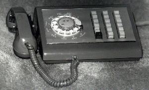
The most commonly used telephone sets for the 1A2 systems were modifications of the Bell System standard 500-series telephones for rotary dial systems, and the 2500-series Touch-Tone desk sets. For key system operation these sets were equipped with a set of push-buttons (keys) and additional internal contact springs to control the additional operational features, resulting in a large variety of specialty telephones. Specifically, such telephone sets were the types 565 (up to 5 lines), 630 (17 lines), 631 (29 lines), 830 (9 lines), and 831 (19 lines). Telephone sets could be either rotary dial models, or be equipped with Touch-Tone keypads.
A power supply was either mounted within the panel or separately nearby. The power supply provided 24 VDC for relay operation, filtered 24 VDC for talk battery (intercom and direct-line services), 10 VAC for lamps, 18 VAC for buzzers, and 90-110 VAC at 30Hz for ringers. Lamp and signaling voltages were routed through a mechanical interrupter, to create lamp flash (incoming line), lamp wink (hold), and interrupted buzzer and ringing.
Wiring
Wiring between system components and telephone sets was facilitated by Type 66 punch-down blocks.
For each telephone line from the central office, a key system required five pairs of internal wires: The central office tip and ring leads, the station (telephone instrument) tip and ring wires, the A and A1 control leads, lamp power and lamp ground, and the ring signaling pair.
Each connection to a telephone set required six wires from the key system: One pair (two wires) carried the talk circuit (tip and ring), one pair carried control information, known as A-Leads, for that line, designated A and A1, and the third pair carried current to a lamp for the specific line key position on the telephone set (L and LG).
A telephone set (keyset) could operate as many lines as it had pickup keys (buttons) installed. Most keysets with up to nine lines are connected to the system using a single 25-pair cable terminated with an Amphenol 50-position "MicroRibbon" connector. Sets with up to 19 line positions used a 50-pair cable and the large instruments with 29 line positions used 75 pairs on three connectors. The Call Director model telephone had over 30 line key positions, and used 100 pairs on four connectors.
The keyset cables were typically routed to a wiring closet or wiring panel where the Key Service Unit (KSU) was installed and were terminated on a 66 type punch block, typically a model 66M1-50. Each of these blocks could accept two 25-pair cables for termination.
Cross-connect wire jumpers, consisting of three twisted pairs were installed between these blocks and the larger distribution connecting blocks within the KSU for each line provided to the telephone set.
Large 1A2 installations had multiple wiring closets fed by branch cables extended from the central closet where the KSU was located. An example of this type of installation would be a multi-story building. The KSU and incoming lines might be in the basement, while each floor had a branch wiring closet to which the telephones on that floor were connected.
User interface
A user could select any available telephone line by pressing the appropriate pickup key and taking the handset off-hook. While on a telephone call, a user could place the call on hold by pressing the hold button, which also released the depressed line button mechanically, enabling the user to select another line for placing a call.
A user might have a set with just a few lines available, while the system attendant or receptionist might have a set wired for many more lines so that they could monitor the status of all lines simultaneously.
Key telephone systems also supported manual buzzers, intercom lines (with or without selective ringing), music on hold, and other features. The features were provided on a line-by-line basis by the selection of particular Key Telephone Units (KTUs) plugged into a pre-wired backplane in the central control unit.
Optional components of the 1A2 could also provide a function called 'I-Hold,' where a call could only be retrieved off hold at the phone that originally placed the line in the hold mode. The cadence of the 'I-Hold' lamp signal was steady illumination punctuated by a series of rapid blinks (produced by a module called a 'flutter generator') every couple of seconds.
Unlike most later electronic key systems or PBXs, 1A2 systems remain partially functional in the event of a local power failure. The telephones may still be used to make and receive calls when the central office is available, but the system is unable to provide visual or audible supervision, as well as hold functions and intercom services during power outages. Central-office powered ringers continue to function and by designating one telephone ringer per line it is possible to identify the line that is ringing.
Audible supervision
Audible signals, most often from ringers or buzzers, could be handled several ways. The ringer in a specific telephone set could be hardwired to one specific phone line. This had the advantage that the phone would ring any time a call came in on that specific line, even during a local power failure, but it also had the disadvantage of limiting ringing to that one line. No other lines could be connected to that ringer.
Another method, sometimes known as common audible, utilizes the internal circuitry of the KSU power supply, and circuitry in the individual key telephone units serving each line, to provide a separate and locally generated ringing signal for each phone line. This has the advantage that the ringing signal for any given line may be routed to any phone, or combinations of phones, but it also had the disadvantage of being non-functional during a local power outage.
A combination of these methods was possible. A set of relays were continuously powered by the power supply. The common-audible ringing signals from the KSU would run though the energized relays to certain phones that would also ring if there was a power failure. The phone lines that terminated at the KSU were also terminated at these relays and in the event of a power failure, the relays would de-energize and switch the phone lines to the ringers of selected phones.
Buzzers were not usually designed to accommodate the 90-110 volt, 20–30Hz ringing signal used by telephone ringers. Instead, they usually operated on low-voltage AC (10-18 volts) supplied by the power supply.
Visual supervision
The buttons on telephone sets were transparent to provide visual signals furnished by lamps installed underneath the buttons in the telephone set. This permitted the user to instantly determine the status of the telephone lines available at the set:
Deployment
The 1A2 system is uncommon today, but some very large installations are still in use because of the high cost of replacing them. 1A2 systems are also still popular at radio stations. This is because, being analog, they are easily connected through a telephone hybrid into the studio's audio equipment for switching calls into broadcast signals.
Despite the fact that 1A2 systems have widely been replaced by newer electronic key systems or PBXs, the simple and modular design of the 1A2's components provide a degree of versatility and reliability that few of its modern successors can match. 1A2 equipment may still be seen in service in places like emergency operations centers, and older police and fire stations.