
 | ||
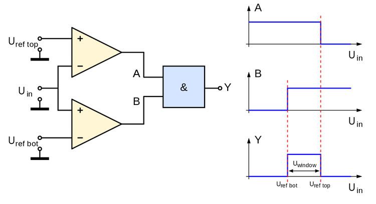
A window detector circuit, also called window comparator circuit or dual edge limit detector circuits is used to determine whether an unknown input is between two precise reference threshold voltages. It employs two comparators to detect over-voltage or under-voltage.
Each single comparator detects the common input voltage against one of two reference voltages, normally upper and lower limits. Outputs behind a logic gate like AND detect the input as in range of the so-called "window" between upper and lower reference.
Window detectors used in industrial alarms, level sensor and controls, digital computers and production-line testing.
Function
If Vin is greater than V1 and V2 (Vin > 2/3 Vcc) then the comparator CMP1 output will swing to the logical low and make the TR2 to turn OFF (LED2 OFF), while the comparator CMP2 output will swing to the logical high; this will power the TR1 base make the TR1 to turn ON (LED1 ON).
When the Vin is less than V1 but greater than V2 (1/3 Vcc < Vin < 2/3 Vcc) then the comparator CMP1 output will swing to logical high and make the TR2 to turn ON (LED2 ON). The comparator CMP2 output also will swing to the logical high; this will provide the necessary voltage input on the TR1 base to make it ON (LED1 ON).
The last when the Vin voltage goes below the V1 and V2 (Vin < 1/3 Vcc) then the comparator CMP1 output will swing to logical high and make the TR2 to turn ON (LED2 ON), while the comparator CMP2 output will swing to the logical low and make the TR1 to turn OFF (LED1 OFF).