
 | ||
Wheel Impact Phase Detection (WIPD ™ ) is an internationally patented electronic wheel impact and wheel flat seismic rail sensing method developed primarily for the North American railroad industry. - courtesy of RailTek Systems.
Consisting of Seismic sensors near or attached to a rail track performing seismic wave phase analysis that can very accurately detect wheel failures. The system can be installed as a permanent installation or through mobile deployable stations. These sensor stations can then be deployed strategically across major rail arteries.
The WIPD ™ systems are used in combination with seismic sensors, RFID, High Speed Cameras, Weighing load cells, Axle Counters, thermal imaging (FLIR) and post processing computers connected wired or wirelessly to enhance the results provided by the WIPD ™ device.
SEISMIC SENSORS
Typically 4 seismic sensors are used per WIPD ™, two sensors per track. These seismic sensors might be any electronic device capable of translating seismic vibrations through gas or other more dense mediums, to high frequency electric waves. Typical seismic sensors used are piezoelectric elements, microphones, geophones, MEMS, strain gauges, pressure transducers or electro-mechanical designs such as LVDTs etc. Contactless velocity measurement sensors such as lasers can also be used, however optical devices require special attention to prohibit signal path obstruction and lens contamination. Optical measurement requires special attention to ensure a consistent linear calibrated response.
All seismic sensors types can be either through hole bolted, glued, clamped or magnetically attached to the rail track.
RFID
Each rail car is equipped with at least two RFID tags to provide a means of identifying a particular rail car.
HIGH-SPEED CAMERAS AND IMAGE ANALYSIS
The WIPD ™ device can capture and calculate the absolute position of the faulty wheel in real time at speeds up to 500 km/h and can calculate the relative position to the sensors within millimeters. This relative position can be used to visually indicate the faulty wheel in a high-speed strobe triggered image, video or audio track tagging for post analysis - this might includes thermal image markers for hot bearings. It is then possible to fully automate the process of identifying the rail car, wheel position and provide a wheel impulse signature, using optical or digital trace markers, for post analysis in a central or remote database repository. Automated image character recognition can be used to fully automate the identification process of faulty rail cars.
AXLE COUNTERS
Axle counters can be used in conjunction with the WIPD ™ device to correlate the faulty wheel with the train axle counter. Axle counter assemblies can be bolted or clamped to the rail.
WEIGHING LOAD CELLS
Since the WIPD ™ device allows for a system setup with all the necessary infrastructure, such as the WIPD ™ device in combination with high-speed cameras and/or axle counters and the RFID reader. The WIPD ™ device also provide load cell inputs to capture out of bounds wheel load measurements. If a wheel exceed a maximum weight or if the axle is excessively unbalanced the strobe output can be triggered to record the event.
The load cells can also be used as a rudimentary axle counter. Load cells can also take the place of the seismic elements to measure the seismic phase impulses as opposed to using MEMS or piezoelectric type seismic sensors. Load cell assemblies can be bolted, clamped or strain gauges might be glued directly to rail.
The advantage of the WIPD ™ method is that it is significantly less complicated and a much cheaper solution than existing WILD systems.
TIME CORRELATED IMPACT MEASUREMENT
Train entry and exit signaling can be used to measure a train running at approximate constant speed. An internal WIPD ™ train length timer can be initiated while a WIPD impact trigger can be used to record the relative timed train faulty wheel position. Post analysis will allow the operator to calculate the rail car index based on the relative time offset within the total train timer length.
VISUAL INDICATIVE PAINT MARKERS
The precise high speed measurements of the WIPD™ allows for the use of paint ball cannons to be used to be synchronously triggered to mark faulty wheels with a color dye. This marker dye can for instance be of fluorescent (UV sensitive) or environmentally friendly paint types. This option would be particularly useful for situations where poor infrastructure in underdeveloped geographical areas exist.
WIPD ™ detectors are used in conjunction with RFID sensors mounted on each side of rolling stock and active trackside readers, AEI uses RF technology to identify railroad equipment while en route.
Development
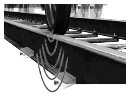
The WIPD ™ phase sensing method uses two or more seismic sensors connected to the side of a rail track to capture seismic noise generated by railcar wheels.
A wheel that exceeds a preset seismic noise threshold in amplitude, will trigger a wheel tracking algorithm that calculates seismic phase shift data related to the actively tracked wheel noise level, to determine the precise location, in real time, of the faulty wheel carriage while moving at full speed. With the sensors spaced from each other such that seismic phase time propagation delays between sensors, in relation to the signal source, can be measured to calculate the exact position of the faulty wheel in real time. Knowing the precise location of the tracked wheel allows the system to isolate the railcar and capture the railcar and wheel carriage identification information.
The WIPD ™ system is protected by international patents by a Canadian inventor - Frank C van der Merwe.