.jpg)
Microprocessor and Programming

The Intel 8085 ("eighty-eighty-five") is an 8-bit microprocessor introduced by Intel in 1977. It was backward binary compatible with the more-famous Intel 8080 (only adding a few minor instructions) but required less supporting hardware, thus allowing simpler and less expensive microcomputer systems to be built.
The "5" in the model number came from the fact that the 8085 requires only a +5-Volt (V) power supply by using depletion mode transistors, rather than requiring the +5 V, ?5 V and +12 V supplies the 8080 needed. This is similar to the competing Z80 (also 8080-derived) introduced the year before. These processors were sometimes used in computers running the CP/M operating system.
The Intel 8085 required at least an external ROM and RAM and an 8 bit address latch (both latches combined in the Intel 8755 2Kx8 EPROM / 2x8 I/O, Intel 8155 256-byte RAM and 22 I/O and 14 bit programmable Timer/Counter) so cannot technically be called a microcontroller.
Both designs (8080/8085) were eclipsed for desktop computers by the compatible Zilog Z80, which took over most of the CP/M computer market as well as taking a share of the booming home computer market in the early-to-mid-1980s.
The 8085 had a long life as a controller. Once designed into such products as the DECtape controller and the VT100 video terminal in the late 1970s, it served for new production throughout the life span of those products (generally longer than the product life of desktop computers).
Pro-Log Corp. put the 8085 and supporting hardware on an STD Bus format card containing CPU, RAM, sockets for ROM/EPROM, I/O and external bus interfaces. The included Instruction Set Reference Card used entirely different mnemonics for the Intel 8085 CPU, as the product was a direct competitor to Intels Multibus card offerings.
Description
The 8085 is a conventional von Neumann design based on the Intel 8080. Unlike the 8080 it does not multiplex state signals onto the data bus, but the 8-bit data bus was instead multiplexed with the lower part of the 16-bit address bus to limit the number of pins to 40. Pin No. 40 is used for the power supply (+5 V) and pin No. 20 for ground. Pin No. 39 is used as the hold pin. Pins No. 15 to No. 8 are generally used for address buses. The processor was designed using nMOS circuitry and the later "H" versions were implemented in Intels enhanced nMOS process called HMOS, originally developed for fast static RAM products. Only a 5 volt supply is needed, like competing processors and unlike the 8080. The 8085 uses approximately 6,500 transistors.
The 8085 incorporates the functions of the 8224 (clock generator) and the 8228 (system controller), increasing the level of integration. A downside compared to similar contemporary designs (such as the Z80) was the fact that the buses required demultiplexing; however, address latches in the Intel 8155, 8355, and 8755 memory chips allowed a direct interface, so an 8085 along with these chips was almost a complete system.
The 8085 has extensions to support new interrupts, with three maskable interrupts (RST 7.5, RST 6.5 and RST 5.5), one non-maskable interrupt (TRAP), and one externally serviced interrupt (INTR). The RST n.5 interrupts refer to actual pins on the processor, a feature which permitted simple systems to avoid the cost of a separate interrupt controller.
Like the 8080, the 8085 can accommodate slower memories through externally generated wait states (pin 35, READY), and has provisions for Direct Memory Access (DMA) using HOLD and HLDA signals (pins 39 and 38). An improvement over the 8080 was that the 8085 can itself drive a piezoelectric crystal directly connected to it, and a built in clock generator generates the internal high amplitude two-phase clock signals at half the crystal frequency (a 6.14 MHz crystal would yield a 3.07 MHz clock, for instance).
The 8085 is a binary compatible follow up on the 8080, using the same basic instruction set as the 8080. Only a few minor instructions were new to the 8085 above the 8080 set
Applications
For the extensive use of 8085 in various applications, the microprocessor is provided with an instruction set which consists of various instructions such as MOV, ADD, SUB, JMP, etc. These instructions are written in the form of a program which is used to perform various operations such as branching, addition, subtraction, bitwise logical and bit shift operations. More complex operations and other arithmetic operations must be implemented in software. For example, multiplication is implemented using a multiplication algorithm.
The 8085 processor was used in a few early personal computers, for example, the TRS-80 Model 100 line used an OKI manufactured 80C85 (MSM80C85ARS). The CMOS version 80C85 of the NMOS/HMOS 8085 processor has several manufacturers. Some manufacturers provide variants with additional functions such as additional instructions.[citation needed] The rad-hard version of the 8085 has been in on-board instrument data processors for several NASA and ESA space physics missions in the 1990s and early 2000s, including CRRES, Polar, FAST, Cluster, HESSI, the Sojourner Mars Rover, and THEMIS. The Swiss company SAIA used the 8085 and the 8085-2 as the CPUs of their PCA1 line of programmable logic controllers during the 1980s.
Features of 8085
It is an 8 bit microprocessor (each character is represented by 8 bits or a byte).
It is manufactured with N-MOS (n-type Metal Oxide Semiconductor) technology implemented with 6200 transistors.
It has 16-bit address lines - A0-A15 (to point the memory locations) and hence can point up to 2^16 = 65535 bytes (64KB) memory locations.
The first 8 lines of address bus and 8 lines of data bus are multiplexed AD0-AD7. Data bus is a group of 8 lines D0-D7.
It provides 5 level interrupts and supports external interrupt request.
A 16 bit program counters (PC).
A 16 bit stack pointer (SP).
It provides 1 accumulator, 2 flag register, six 8-bit general purpose register arranged in pairs: BC, DE, HL and 2special purpose registers.
It consists of 74 instruction sets.
It performs arithmetic and logical operations.
It provides status for advanced control signals, On chip clock generator.
It requires a signal +5V power supply and operates at 3.2 MHZ single phase clock with maximum clock frequency 6 MHz and minimum clock frequency 500 kHz.
Serial input/output port.
1.3 micro sec instruction cycles.
It is enclosed with 40 pins DIP (Dual in line package).
It can be used to implement (interface) 3 chip micro-computers (8085, 8155, 8255 and 8355: Peripheral ICs).
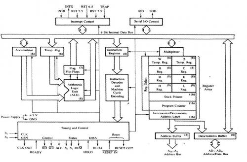
Achitecture of 8085
Microprocessor 8086
The 8086 ("eighty-eighty-six", also called iAPX 86) is a 16-bit microprocessor chip designed by Intel between early 1976 and mid-1978, when it was released. The Intel 8088, released in 1979, was a slightly modified chip with an external 8-bit data bus (allowing the use of cheaper and fewer supporting ICs), and is notable as the processor used in the original IBM PC design, including the widespread version called IBM PC XT. The 8086 gave rise to the x86 architecture which eventually turned out as Intels most successful line of processors.

The first x86 design
The 8086 project started in May 1976 and was originally intended as a temporary substitute for the ambitious and delayed iAPX 432 project. It was an attempt to draw attention from the less-delayed 16 and 32-bit processors of other manufacturers (such as Motorola, Zilog, and National Semiconductor) and at the same time to counter the threat from the Zilog Z80 (designed by former Intel employees), which became very successful. Both the architecture and the physical chip were therefore developed rather quickly by a small group of people, and using the same basic microarchitecture elements and physical implementation techniques as employed for the slightly older 8085 (and for which the 8086 also would function as a continuation).
Marketed as source compatible, the 8086 was designed to allow assembly language for the 8008, 8080, or 8085 to be automatically converted into equivalent (sub-optimal) 8086 source code, with little or no hand-editing. The programming model and instruction set was (loosely) based on the 8080 in order to make this possible. However, the 8086 design was expanded to support full 16-bit processing, instead of the fairly basic 16-bit capabilities of the 8080/8085.
The architecture was defined by Stephen P. Morse with some help and assistance by Bruce Ravenel (the architect of the 8087) in refining the final revisions. Logic designer Jim McKevitt and John Bayliss were the lead engineers of the hardware-level development team[note 10] and William Pohlman the manager for the project. The legacy of the 8086 is enduring in the basic instruction set of todays personal computers and servers; the 8086 also lent its last two digits to later extended versions of the design, such as the Intel 286 and the Intel 386, all of which eventually became known as the x86 family. (Another reference is that the PCI Vendor ID for Intel devices is 8086h.)
Details
Buses and operation
All internal registers, as well as internal and external data buses, were 16 bits wide, firmly establishing the "16-bit microprocessor" identity of the 8086. A 20-bit external address bus gave a 1 MB physical address space (220 = 1,048,576). This address space was addressed by means of internal segmentation. The data bus was multiplexed with the address bus in order to fit a standard 40-pin dual in-line package. 16-bit I/O addresses meant 64 KB of separate I/O space (216 = 65,536). The maximum linear address space was limited to 64 KB, simply because internal registers were only 16 bits wide. Programming over 64 KB boundaries involved adjusting segment registers (see below) and remained so until the 80386 introduced wider (32 bits) main registers (the memory management hardware in the 286 did not help in this regard, as registers were still 16 bits).
Some of the control pins, which carry essential signals for all external operations, had more than one function depending upon whether the device was operated in min or max mode. The former was intended for small single processor systems while the latter was for medium or large systems, using more than one processor.
Registers and instructions
The 8086 has eight more or less general 16-bit registers (including the stack pointer but excluding the instruction pointer, flag register and segment registers). Four of them, AX, BX, CX, DX, could also be accessed as twice as many 8-bit registers (see figure) while the other four, BP, SI, DI, SP, were 16-bit only.
Due to a compact encoding inspired by 8-bit processors, most instructions were one-address or two-address operations which means that the result was stored in one of the operands. At most one of the operands could be in memory, but this memory operand could also be the destination, while the other operand, the source, could be either register or immediate. A single memory location could also often be used as both source and destination which, among other factors, further contributed to a code density comparable to (and often better than) most eight bit machines.
Although the degree of generality of most registers were much greater than in the 8080 or 8085, it was still fairly low compared to the typical contemporary minicomputer, and registers were also sometimes used implicitly by instructions. While perfectly sensible for the assembly programmer, this made register allocation for compilers more complicated compared to more regular 16- and 32-bit processors such as the PDP-11, VAX, 68000, etc. On the other hand, compared to semi-contemporary simple, popular and ubiquitous 8-bit microprocessors such as MOS Technology 6502, Motorola 6809, Intel 8085, Intel 8051, and similar, it was significantly easier to generate code for the 8086 design.

The 8086 also featured 64 KB of 8-bit (or alternatively 32 K-word of 16-bit) I/O space. A 64 KB (one segment) stack growing towards lower addresses is supported in hardware; 2-byte words are pushed to the stack and the stack top is pointed to by SS:SP. There are 256 interrupts, which can be invoked by both hardware and software. The interrupts can cascade, using the stack to store the return addresses.
The processor had some new instructions (not present in the 8080 and 8085) to better support stack based high level programming languages such as Pascal and PL/M; some of the more useful ones were push mem-op, and ret size, supporting the "pascal calling convention" directly. (Several others, such as push immed and enter, would be added in the subsequent 80186, 80286, and 80386 designs.)
Flags
8086 has a 16-bit flags register. Nine of these condition code flags are active, and indicate the current state of the processor: Carry flag (CF), Parity flag (PF), Auxiliary carry flag (AF), Zero flag (ZF), Sign flag (SF), Trap flag (TF), Interrupt flag (IF), Direction flag (DF), and Overflow flag (OF).
Segmentation
There are also four 16-bit segment registers (see figure) that allow the 8086 CPU to access one megabyte of memory in an unusual way. Rather than concatenating the segment register with the address register, as in most processors whose address space exceeded their register size, the 8086 shifts the 16-bit segment only four bits left before adding it to the 16-bit offset (16×segment + offset), therefore producing a 20-bit external (or effective or physical) address from the 32-bit segment:offset pair. As a result, each external address can be referred to by 212 = 4096 different segment:offset pairs.
Floating point
The 8086/8088 could be connected to a mathematical coprocessor to add hardware/microcode-based floating point performance. The Intel 8087 was the standard math coprocessor for the 8086 and 8088, operating on 80-bit numbers. Manufacturers like Cyrix (8087-compatible) and Weitek (non 8087-compatible) eventually came up with high performance floating point co-processors that competed with the 8087 as well as with the sub
Hardware modes
The 8086 and 8088 support two hardware modes: maximum mode and minimum mode. Maximum mode is for large applications such as multiprocessing and is also required to support the 8087 coprocessor. The mode is usually hard-wired into the circuit and cannot be changed by software. Specifically, pin #33 (MN/MX) is either wired to voltage or to ground to determine the mode. Changing the state of pin #33 changes the function of certain other pins, most of which have to do with how the CPU handles the (local) bus. The IBM PC and PC/XT use an Intel 8088 running in maximum mode, which allows the CPU to work with an optional 8087 coprocessor installed in the math coprocessor socket on the PC or PC/XT mainboard. (The PC and PC/XT may require Max mode for other reasons, such as perhaps to support the DMA controller.)
Microcomputers using the 8086
Seattle Computer Products shipped S-100 bus based 8086 systems (SCP200B) as early as November 1979.
The Norwegian Mycron 2000, introduced in 1980.
One of the most influential microcomputers of all, the IBM PC, used the Intel 8088, a version of the 8086 with an eight-bit data bus.
The first Compaq Deskpro used an 8086 running at 7.14 MHz, (?) but was capable of running add-in cards designed for the 4.77 MHz IBM PC XT.
An 8 MHz 8086 was used in the AT&T 6300 PC (built by Olivetti), an IBM PC-compatible desktop microcomputer. The M24 / PC 6300 has IBM PC/XT compatible 8-bit expansion slots, but some of them have a proprietary extension providing the full 16-bit data bus of the 8086 CPU (similar in concept to the 16-bit slots of the IBM PC AT, but different in the design details, and physically incompatible).
The IBM PS/2 models 25 and 30 were built with an 8 MHz 8086.
The Amstrad/Schneider PC1512, PC1640, PC2086, PC3086 and PC5086 all used 8086 CPUs at 8 MHz.
The NEC PC-9801.
The Tandy 1000 SL-series and RL machines used 8086 CPUs.
The IBM Displaywriter word processing machine[7] and the Wang Professional Computer, manufactured by Wang Laboratories, also used the 8086.
NASA used original 8086 CPUs on equipment for ground-based maintenance of the Space Shuttle Discovery until the end of the space shuttle program in 2011. This decision was made to prevent software regression that might result from upgrading or from switching to imperfect clones.
KAMAN Process and Area Radiation Monitors
Architecture of 8086

8086 instructions
The Art of Assembly Language Programming (AoA), Randy Hydes acclaimed text on assembly language programming, is the most-often recommended book on 80x86 assembly language programming in newsgroups, on web sites, and by word of mouth. Why? Well, here are a few reasons:
AoA is comprehensive,
AoA is easy to read and understand,
AoA has had over 15 years refinement,
AoA teaches the fundamentals one must know to be considered an assembly language programmer, and
AoA was written by a recognized expert in x86 assembly language programming.
purpose of procedure and macros
Macros and procedures
Procedure
Definition of procedure
A procedure is a collection of instructions to which we can direct the flow of our program, and once the execution of these instructions is over control is given back to the next line to process of the code which called on the procedure.
Procedures help us to create legible and easy to modify programs.
At the time of invoking a procedure the address of the next instruction of the program is kept on the stack so that, once the flow of the program has been transferred and the procedure is done, one can return to the next line
of the original program, the one which called the procedure.
Syntax of a Procedure
There are two types of procedures, the intrasegments, which are found on the same segment of instructions, and the inter-segments which can be stored on different memory segments.
When the intrasegment procedures are used, the value of IP is stored on the stack and when the intrasegments are used the value of CS:IP is stored.
To divert the flow of a procedure (calling it), the following directive is used:
CALL NameOfTheProcedure
The part which make a procedure are:
Declaration of the procedure
Code of the procedure
Return directive
Termination of the procedure
For example, if we want a routine which adds two bytes stored in AH and AL
each one, and keep the addition in the BX register:
Adding Proc Near ; Declaration of the procedure
Mov Bx, 0 ; Content of the procedure
Mov B1, Ah
Mov Ah, 00
Add Bx, Ax
Ret ; Return directive
Add Endp ; End of procedure declaration
On the declaration the first word, Adding, corresponds to the name of out procedure, Proc declares it as such and the word Near indicates to the MASM that the procedure is intrasegment. The Ret directive loads the IP address stored on the stack to return to the original program, lastly, the Add Endp directive indicates the end of the procedure.
To declare an inter segment procedure we substitute the word Near for the word FAR.
The calling of this procedure is done the following way:
Call Adding Macros offer a greater flexibility in programming compared to theprocedures, nonetheless, these last ones will still be used.
Macros
Definition of the macro
A macro is a gro of repetitive instructions in a program which arecodified only once and can be used as many times as necessary.
The main difference between a macro and a procedure is that in the macro the passage of parameters is possible and in the procedure it is not, this is only applicable for the TASM - there are other programming languages which do allow it. At the moment the macro is executed each parameter is substituted by the name or value specified at the time of the call.
We can say then that a procedure is an extension of a determined program, while the macro is a module with specific functions which can be used by different programs.
Another difference between a macro and a procedure is the way of calling each one, to call a procedure the use of a directive is required, on the other hand the call of macros is done as if it were an assembler instruction.
Syntax of a Macro
The parts which make a macro are:
Declaration of the macro
Code of the macro
Macro termination directive
The declaration of the macro is done the following way:
NameMacro MACRO [parameter1, parameter2...]
Even though we have the functionality of the parameters it is possible to create a macro which does not need them.
The directive for the termination of the macro is: ENDM
An example of a macro, to place the cursor on a determined position on the screen is:
Position MACRO Row, Column
PUSH AX
PUSH BX
PUSH DX
MOV AH, 02H
MOV DH, Row
MOV DL, Column
MOV BH, 0
INT 10H
POP DX
POP BX
POP AX
ENDM
To use a macro it is only necessary to call it by its name, as if it were another assembler instruction, since directives are no longer necessary as in the case of the procedures. Example:
Position 8, 6
Macro Libraries
One of the facilities that the use of macros offers is the creation of libraries, which are groups of macros which can be included in a program from a different file.
The creation of these libraries is very simple, we only have to write a file with all the macros which will be needed and save it as a text file.
To call these macros it is only necessary to use the following instruction Include NameOfTheFile, on the part of our program where we would normally write the macros, this is, at the beginning of our program, before the
declaration of the memory model.
The Intel 8085 ("eighty-eighty-five") is an 8-bit microprocessor introduced by Intel in 1977. It was backward binary compatible with the more-famous Intel 8080 (only adding a few minor instructions) but required less supporting hardware, thus allowing simpler and less expensive microcomputer systems to be built.
The "5" in the model number came from the fact that the 8085 requires only a +5-Volt (V) power supply by using depletion mode transistors, rather than requiring the +5 V, ?5 V and +12 V supplies the 8080 needed. This is similar to the competing Z80 (also 8080-derived) introduced the year before. These processors were sometimes used in computers running the CP/M operating system.
The Intel 8085 required at least an external ROM and RAM and an 8 bit address latch (both latches combined in the Intel 8755 2Kx8 EPROM / 2x8 I/O, Intel 8155 256-byte RAM and 22 I/O and 14 bit programmable Timer/Counter) so cannot technically be called a microcontroller.
Both designs (8080/8085) were eclipsed for desktop computers by the compatible Zilog Z80, which took over most of the CP/M computer market as well as taking a share of the booming home computer market in the early-to-mid-1980s.
The 8085 had a long life as a controller. Once designed into such products as the DECtape controller and the VT100 video terminal in the late 1970s, it served for new production throughout the life span of those products (generally longer than the product life of desktop computers).
Pro-Log Corp. put the 8085 and supporting hardware on an STD Bus format card containing CPU, RAM, sockets for ROM/EPROM, I/O and external bus interfaces. The included Instruction Set Reference Card used entirely different mnemonics for the Intel 8085 CPU, as the product was a direct competitor to Intels Multibus card offerings.
Description
The 8085 is a conventional von Neumann design based on the Intel 8080. Unlike the 8080 it does not multiplex state signals onto the data bus, but the 8-bit data bus was instead multiplexed with the lower part of the 16-bit address bus to limit the number of pins to 40. Pin No. 40 is used for the power supply (+5 V) and pin No. 20 for ground. Pin No. 39 is used as the hold pin. Pins No. 15 to No. 8 are generally used for address buses. The processor was designed using nMOS circuitry and the later "H" versions were implemented in Intels enhanced nMOS process called HMOS, originally developed for fast static RAM products. Only a 5 volt supply is needed, like competing processors and unlike the 8080. The 8085 uses approximately 6,500 transistors.
The 8085 incorporates the functions of the 8224 (clock generator) and the 8228 (system controller), increasing the level of integration. A downside compared to similar contemporary designs (such as the Z80) was the fact that the buses required demultiplexing; however, address latches in the Intel 8155, 8355, and 8755 memory chips allowed a direct interface, so an 8085 along with these chips was almost a complete system.
The 8085 has extensions to support new interrupts, with three maskable interrupts (RST 7.5, RST 6.5 and RST 5.5), one non-maskable interrupt (TRAP), and one externally serviced interrupt (INTR). The RST n.5 interrupts refer to actual pins on the processor, a feature which permitted simple systems to avoid the cost of a separate interrupt controller.
Like the 8080, the 8085 can accommodate slower memories through externally generated wait states (pin 35, READY), and has provisions for Direct Memory Access (DMA) using HOLD and HLDA signals (pins 39 and 38). An improvement over the 8080 was that the 8085 can itself drive a piezoelectric crystal directly connected to it, and a built in clock generator generates the internal high amplitude two-phase clock signals at half the crystal frequency (a 6.14 MHz crystal would yield a 3.07 MHz clock, for instance).
The 8085 is a binary compatible follow up on the 8080, using the same basic instruction set as the 8080. Only a few minor instructions were new to the 8085 above the 8080 set
Applications
For the extensive use of 8085 in various applications, the microprocessor is provided with an instruction set which consists of various instructions such as MOV, ADD, SUB, JMP, etc. These instructions are written in the form of a program which is used to perform various operations such as branching, addition, subtraction, bitwise logical and bit shift operations. More complex operations and other arithmetic operations must be implemented in software. For example, multiplication is implemented using a multiplication algorithm.
The 8085 processor was used in a few early personal computers, for example, the TRS-80 Model 100 line used an OKI manufactured 80C85 (MSM80C85ARS). The CMOS version 80C85 of the NMOS/HMOS 8085 processor has several manufacturers. Some manufacturers provide variants with additional functions such as additional instructions.[citation needed] The rad-hard version of the 8085 has been in on-board instrument data processors for several NASA and ESA space physics missions in the 1990s and early 2000s, including CRRES, Polar, FAST, Cluster, HESSI, the Sojourner Mars Rover, and THEMIS. The Swiss company SAIA used the 8085 and the 8085-2 as the CPUs of their PCA1 line of programmable logic controllers during the 1980s.
Features of 8085
It is an 8 bit microprocessor (each character is represented by 8 bits or a byte).
It is manufactured with N-MOS (n-type Metal Oxide Semiconductor) technology implemented with 6200 transistors.
It has 16-bit address lines - A0-A15 (to point the memory locations) and hence can point up to 2^16 = 65535 bytes (64KB) memory locations.
The first 8 lines of address bus and 8 lines of data bus are multiplexed AD0-AD7. Data bus is a group of 8 lines D0-D7.
It provides 5 level interrupts and supports external interrupt request.
A 16 bit program counters (PC).
A 16 bit stack pointer (SP).
It provides 1 accumulator, 2 flag register, six 8-bit general purpose register arranged in pairs: BC, DE, HL and 2special purpose registers.
It consists of 74 instruction sets.
It performs arithmetic and logical operations.
It provides status for advanced control signals, On chip clock generator.
It requires a signal +5V power supply and operates at 3.2 MHZ single phase clock with maximum clock frequency 6 MHz and minimum clock frequency 500 kHz.
Serial input/output port.
1.3 micro sec instruction cycles.
It is enclosed with 40 pins DIP (Dual in line package).
It can be used to implement (interface) 3 chip micro-computers (8085, 8155, 8255 and 8355: Peripheral ICs).
Achitecture of 8085
Microprocessor 8086
The 8086 ("eighty-eighty-six", also called iAPX 86) is a 16-bit microprocessor chip designed by Intel between early 1976 and mid-1978, when it was released. The Intel 8088, released in 1979, was a slightly modified chip with an external 8-bit data bus (allowing the use of cheaper and fewer supporting ICs), and is notable as the processor used in the original IBM PC design, including the widespread version called IBM PC XT. The 8086 gave rise to the x86 architecture which eventually turned out as Intels most successful line of processors.
The first x86 design
The 8086 project started in May 1976 and was originally intended as a temporary substitute for the ambitious and delayed iAPX 432 project. It was an attempt to draw attention from the less-delayed 16 and 32-bit processors of other manufacturers (such as Motorola, Zilog, and National Semiconductor) and at the same time to counter the threat from the Zilog Z80 (designed by former Intel employees), which became very successful. Both the architecture and the physical chip were therefore developed rather quickly by a small group of people, and using the same basic microarchitecture elements and physical implementation techniques as employed for the slightly older 8085 (and for which the 8086 also would function as a continuation).
Marketed as source compatible, the 8086 was designed to allow assembly language for the 8008, 8080, or 8085 to be automatically converted into equivalent (sub-optimal) 8086 source code, with little or no hand-editing. The programming model and instruction set was (loosely) based on the 8080 in order to make this possible. However, the 8086 design was expanded to support full 16-bit processing, instead of the fairly basic 16-bit capabilities of the 8080/8085.
The architecture was defined by Stephen P. Morse with some help and assistance by Bruce Ravenel (the architect of the 8087) in refining the final revisions. Logic designer Jim McKevitt and John Bayliss were the lead engineers of the hardware-level development team[note 10] and William Pohlman the manager for the project. The legacy of the 8086 is enduring in the basic instruction set of todays personal computers and servers; the 8086 also lent its last two digits to later extended versions of the design, such as the Intel 286 and the Intel 386, all of which eventually became known as the x86 family. (Another reference is that the PCI Vendor ID for Intel devices is 8086h.)
Details
Buses and operation
All internal registers, as well as internal and external data buses, were 16 bits wide, firmly establishing the "16-bit microprocessor" identity of the 8086. A 20-bit external address bus gave a 1 MB physical address space (220 = 1,048,576). This address space was addressed by means of internal segmentation. The data bus was multiplexed with the address bus in order to fit a standard 40-pin dual in-line package. 16-bit I/O addresses meant 64 KB of separate I/O space (216 = 65,536). The maximum linear address space was limited to 64 KB, simply because internal registers were only 16 bits wide. Programming over 64 KB boundaries involved adjusting segment registers (see below) and remained so until the 80386 introduced wider (32 bits) main registers (the memory management hardware in the 286 did not help in this regard, as registers were still 16 bits).
Some of the control pins, which carry essential signals for all external operations, had more than one function depending upon whether the device was operated in min or max mode. The former was intended for small single processor systems while the latter was for medium or large systems, using more than one processor.
Registers and instructions
The 8086 has eight more or less general 16-bit registers (including the stack pointer but excluding the instruction pointer, flag register and segment registers). Four of them, AX, BX, CX, DX, could also be accessed as twice as many 8-bit registers (see figure) while the other four, BP, SI, DI, SP, were 16-bit only.
Due to a compact encoding inspired by 8-bit processors, most instructions were one-address or two-address operations which means that the result was stored in one of the operands. At most one of the operands could be in memory, but this memory operand could also be the destination, while the other operand, the source, could be either register or immediate. A single memory location could also often be used as both source and destination which, among other factors, further contributed to a code density comparable to (and often better than) most eight bit machines.
Although the degree of generality of most registers were much greater than in the 8080 or 8085, it was still fairly low compared to the typical contemporary minicomputer, and registers were also sometimes used implicitly by instructions. While perfectly sensible for the assembly programmer, this made register allocation for compilers more complicated compared to more regular 16- and 32-bit processors such as the PDP-11, VAX, 68000, etc. On the other hand, compared to semi-contemporary simple, popular and ubiquitous 8-bit microprocessors such as MOS Technology 6502, Motorola 6809, Intel 8085, Intel 8051, and similar, it was significantly easier to generate code for the 8086 design.
The 8086 also featured 64 KB of 8-bit (or alternatively 32 K-word of 16-bit) I/O space. A 64 KB (one segment) stack growing towards lower addresses is supported in hardware; 2-byte words are pushed to the stack and the stack top is pointed to by SS:SP. There are 256 interrupts, which can be invoked by both hardware and software. The interrupts can cascade, using the stack to store the return addresses.
The processor had some new instructions (not present in the 8080 and 8085) to better support stack based high level programming languages such as Pascal and PL/M; some of the more useful ones were push mem-op, and ret size, supporting the "pascal calling convention" directly. (Several others, such as push immed and enter, would be added in the subsequent 80186, 80286, and 80386 designs.)
Flags
8086 has a 16-bit flags register. Nine of these condition code flags are active, and indicate the current state of the processor: Carry flag (CF), Parity flag (PF), Auxiliary carry flag (AF), Zero flag (ZF), Sign flag (SF), Trap flag (TF), Interrupt flag (IF), Direction flag (DF), and Overflow flag (OF).
Segmentation
There are also four 16-bit segment registers (see figure) that allow the 8086 CPU to access one megabyte of memory in an unusual way. Rather than concatenating the segment register with the address register, as in most processors whose address space exceeded their register size, the 8086 shifts the 16-bit segment only four bits left before adding it to the 16-bit offset (16×segment + offset), therefore producing a 20-bit external (or effective or physical) address from the 32-bit segment:offset pair. As a result, each external address can be referred to by 212 = 4096 different segment:offset pairs.
Floating point
The 8086/8088 could be connected to a mathematical coprocessor to add hardware/microcode-based floating point performance. The Intel 8087 was the standard math coprocessor for the 8086 and 8088, operating on 80-bit numbers. Manufacturers like Cyrix (8087-compatible) and Weitek (non 8087-compatible) eventually came up with high performance floating point co-processors that competed with the 8087 as well as with the sub
Hardware modes
The 8086 and 8088 support two hardware modes: maximum mode and minimum mode. Maximum mode is for large applications such as multiprocessing and is also required to support the 8087 coprocessor. The mode is usually hard-wired into the circuit and cannot be changed by software. Specifically, pin #33 (MN/MX) is either wired to voltage or to ground to determine the mode. Changing the state of pin #33 changes the function of certain other pins, most of which have to do with how the CPU handles the (local) bus. The IBM PC and PC/XT use an Intel 8088 running in maximum mode, which allows the CPU to work with an optional 8087 coprocessor installed in the math coprocessor socket on the PC or PC/XT mainboard. (The PC and PC/XT may require Max mode for other reasons, such as perhaps to support the DMA controller.)
Microcomputers using the 8086
Seattle Computer Products shipped S-100 bus based 8086 systems (SCP200B) as early as November 1979.
The Norwegian Mycron 2000, introduced in 1980.
One of the most influential microcomputers of all, the IBM PC, used the Intel 8088, a version of the 8086 with an eight-bit data bus.
The first Compaq Deskpro used an 8086 running at 7.14 MHz, (?) but was capable of running add-in cards designed for the 4.77 MHz IBM PC XT.
An 8 MHz 8086 was used in the AT&T 6300 PC (built by Olivetti), an IBM PC-compatible desktop microcomputer. The M24 / PC 6300 has IBM PC/XT compatible 8-bit expansion slots, but some of them have a proprietary extension providing the full 16-bit data bus of the 8086 CPU (similar in concept to the 16-bit slots of the IBM PC AT, but different in the design details, and physically incompatible).
The IBM PS/2 models 25 and 30 were built with an 8 MHz 8086.
The Amstrad/Schneider PC1512, PC1640, PC2086, PC3086 and PC5086 all used 8086 CPUs at 8 MHz.
The NEC PC-9801.
The Tandy 1000 SL-series and RL machines used 8086 CPUs.
The IBM Displaywriter word processing machine[7] and the Wang Professional Computer, manufactured by Wang Laboratories, also used the 8086.
NASA used original 8086 CPUs on equipment for ground-based maintenance of the Space Shuttle Discovery until the end of the space shuttle program in 2011. This decision was made to prevent software regression that might result from upgrading or from switching to imperfect clones.
KAMAN Process and Area Radiation Monitors
Architecture of 8086
8086 instructions
Complete 8086 instruction set
Instruction Set of 8086
refer this site for detailed knowledge of 8086 instructions
http://www.electronics.dit.ie/staff/tscarff/8086_instruction_set/8086_instruction_set.html
The Art of Assembly Language Programming 8086 instructions
Complete 8086 instruction set
The Art of Assembly Language Programming (AoA), Randy Hydes acclaimed text on assembly language programming, is the most-often recommended book on 80x86 assembly language programming in newsgroups, on web sites, and by word of mouth. Why? Well, here are a few reasons:
AoA is comprehensive,
AoA is easy to read and understand,
AoA has had over 15 years refinement,
AoA teaches the fundamentals one must know to be considered an assembly language programmer, and
AoA was written by a recognized expert in x86 assembly language programming.
purpose of procedure and macros
Macros and procedures
Procedure
Definition of procedure
A procedure is a collection of instructions to which we can direct the flow of our program, and once the execution of these instructions is over control is given back to the next line to process of the code which called on the procedure.
Procedures help us to create legible and easy to modify programs.
At the time of invoking a procedure the address of the next instruction of the program is kept on the stack so that, once the flow of the program has been transferred and the procedure is done, one can return to the next line
of the original program, the one which called the procedure.
Syntax of a Procedure
There are two types of procedures, the intrasegments, which are found on the same segment of instructions, and the inter-segments which can be stored on different memory segments.
When the intrasegment procedures are used, the value of IP is stored on the stack and when the intrasegments are used the value of CS:IP is stored.
To divert the flow of a procedure (calling it), the following directive is used:
CALL NameOfTheProcedure
The part which make a procedure are:
Declaration of the procedure
Code of the procedure
Return directive
Termination of the procedure
For example, if we want a routine which adds two bytes stored in AH and AL
each one, and keep the addition in the BX register:
Adding Proc Near ; Declaration of the procedure
Mov Bx, 0 ; Content of the procedure
Mov B1, Ah
Mov Ah, 00
Add Bx, Ax
Ret ; Return directive
Add Endp ; End of procedure declaration
On the declaration the first word, Adding, corresponds to the name of out procedure, Proc declares it as such and the word Near indicates to the MASM that the procedure is intrasegment. The Ret directive loads the IP address stored on the stack to return to the original program, lastly, the Add Endp directive indicates the end of the procedure.
To declare an inter segment procedure we substitute the word Near for the word FAR.
The calling of this procedure is done the following way:
Call Adding Macros offer a greater flexibility in programming compared to theprocedures, nonetheless, these last ones will still be used.
Macros
Definition of the macro
A macro is a gro of repetitive instructions in a program which arecodified only once and can be used as many times as necessary.
The main difference between a macro and a procedure is that in the macro the passage of parameters is possible and in the procedure it is not, this is only applicable for the TASM - there are other programming languages which do allow it. At the moment the macro is executed each parameter is substituted by the name or value specified at the time of the call.
We can say then that a procedure is an extension of a determined program, while the macro is a module with specific functions which can be used by different programs.
Another difference between a macro and a procedure is the way of calling each one, to call a procedure the use of a directive is required, on the other hand the call of macros is done as if it were an assembler instruction.
Syntax of a Macro
The parts which make a macro are:
Declaration of the macro
Code of the macro
Macro termination directive
The declaration of the macro is done the following way:
NameMacro MACRO [parameter1, parameter2...]
Even though we have the functionality of the parameters it is possible to create a macro which does not need them.
The directive for the termination of the macro is: ENDM
An example of a macro, to place the cursor on a determined position on the screen is:
Position MACRO Row, Column
PUSH AX
PUSH BX
PUSH DX
MOV AH, 02H
MOV DH, Row
MOV DL, Column
MOV BH, 0
INT 10H
POP DX
POP BX
POP AX
ENDM
To use a macro it is only necessary to call it by its name, as if it were another assembler instruction, since directives are no longer necessary as in the case of the procedures. Example:
Position 8, 6
Macro Libraries
One of the facilities that the use of macros offers is the creation of libraries, which are groups of macros which can be included in a program from a different file.
The creation of these libraries is very simple, we only have to write a file with all the macros which will be needed and save it as a text file.
To call these macros it is only necessary to use the following instruction Include NameOfTheFile, on the part of our program where we would normally write the macros, this is, at the beginning of our program, before the
declaration of the memory model.