.jpg)
INTRODUCTION
Consider a farm field where certain crop is to be grown. The crop needs to be watered at regular interval. There are four sensors buried under the ground at the four corners of the field. The sensors are made of plaster of paris, cement, timber in the ratio of 2:1:1 and buried in upside down position as explained in the sensor section they sense the moisture level in the soil. The sensed parameter is converted into electrical signal and given to the signal conditioner block. Here the signal is amplified and brought to the desired level.
The output of the signal conditioner is given to the microcontroller where the percentage of the moisture (signals) obtained is added and the average percentage of the four signals is calculated. Based on the software program in the microcontroller and the calculated result, the “radio frequency identification protocol (R.F.I.D.)” sends a signal to the control room (Wireless communication) situated within a distance of around 100 meters.
The R.F I.D. receiver (READER) receives the transmitted signal and gives it to the CPU which is again an microcontroller. The program stored in the microcontroller runs the control action which is running the motor which will supply water to the field without personal attention. The software program will be written such that if the moisture level goes below 15% then only the field will be watered. During the process the sensors on the field will measure the percentage increase of the moisture through the above process and when the percentage of the moisture will reach 85% the signal will be transmitted to the control room and the microcontroller at the control room will stop the control action i.e. watering the field.
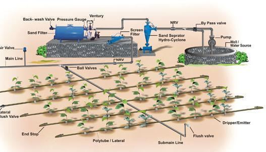
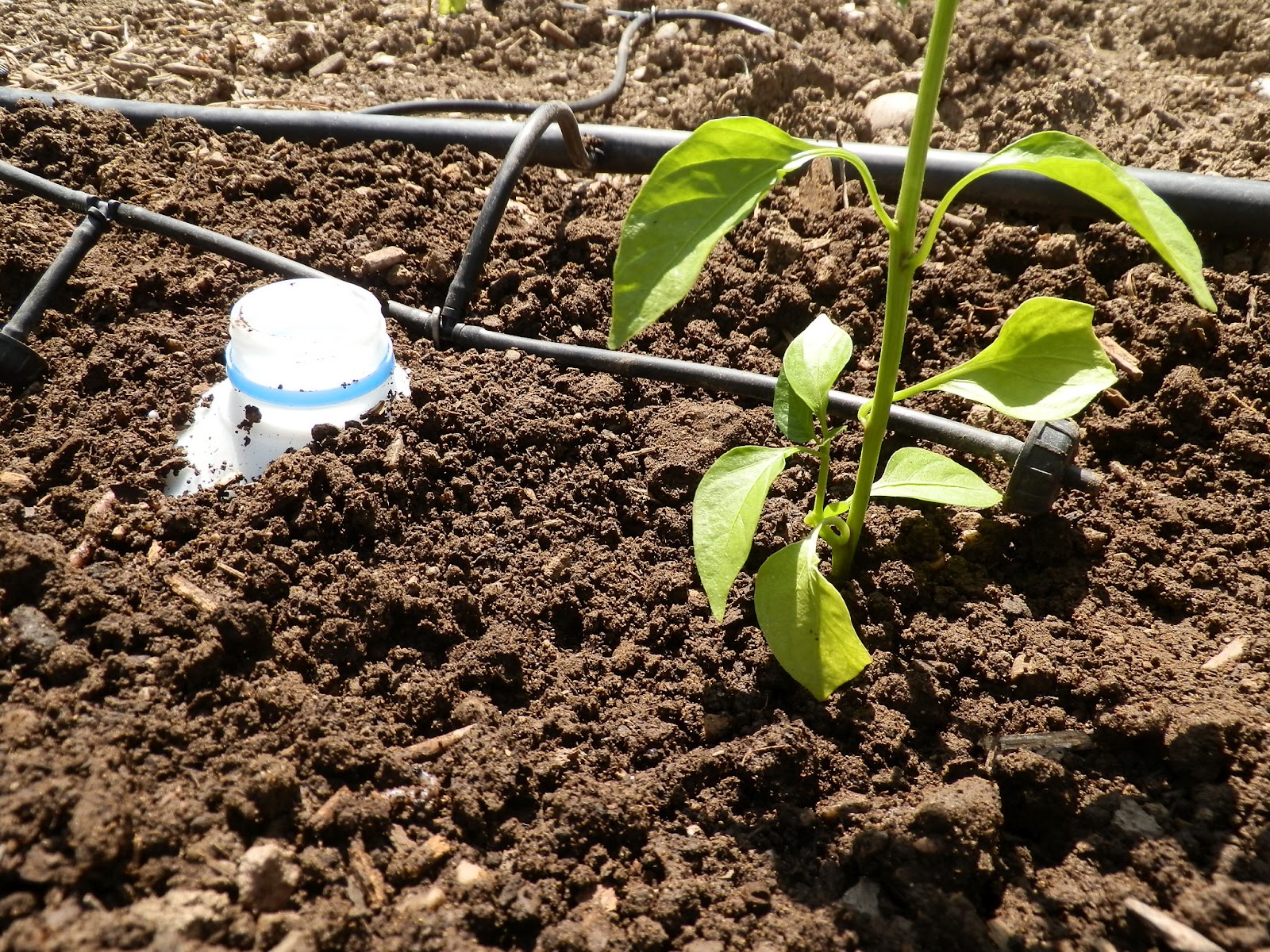
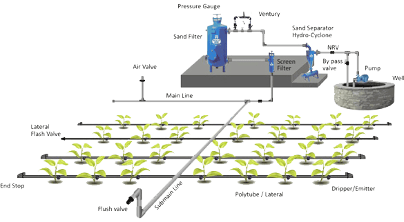
Drip irrigation, also known as trickle irrigation or micro irrigation or localized irrigation, is an irrigation method that saves water and fertilizer by allowing water to drip slowly to the roots of plants, either onto the soil surface or directly onto the root zone, through a network of valves, pipes, tubing, and emitters. It is done through narrow tubes that deliver water directly to the base of the plant.
Most large drip irrigation systems employ some type of filter to prevent clogging of the small emitter flow path by small waterborne particles. New technologies are now being offered that minimize clogging. Some residential systems are installed without additional filters since potable water is already filtered at the water treatment plant. Virtually all drip irrigation equipment manufacturers recommend that filters be employed and generally will not honor warranties unless this is done. Last line filters just before the final delivery pipe are strongly recommended in addition to any other filtration system due to fine particle settlement and accidental insertion of particles in the intermediate lines.
Drip and subsurface drip irrigation is used almost exclusively when using recycled municipal waste water. Regulations typically do not permit spraying water through the air that has not been fully treated to potable water standards.
Because of the way the water is applied in a drip system, traditional surface applications of timed-release fertilizer are sometimes ineffective, so drip systems often mix liquid fertilizer with the irrigation water. This is called fertigation; fertigation and chemigation (application of pesticides and other chemicals to periodically clean out the system, such as chlorine or sulfuric acid) use chemical injectors such as diaphragm pumps, piston pumps, or aspirators. The chemicals may be added constantly whenever the system is irrigating or at intervals. Fertilizer savings of up to 95% are being reported from recent university field tests using drip fertigation and slow water delivery as compared to timed-release and irrigation by micro spray heads.
Properly designed, installed, and managed, drip irrigation may help achieve water conservation by reducing evaporation and deep drainage when compared to other types of irrigation such as flood or overhead sprinklers since water can be more precisely applied to the plant roots. In addition, drip can eliminate many diseases that are spread through water contact with the foliage. Finally, in regions where water supplies are severely limited, there may be no actual water savings, but rather simply an increase in production while using the same amount of water as before. In very arid regions or on sandy soils, the preferred method is to apply the irrigation water as slowly as possible.
Water Use
Water use is measured in terms of inches per acre and varies across the three automated seep and sub-drip replications (six observations). It was hypothesized that replication and irrigation system type (automated seep and drip) could affect water usage. Replication is a proxy for any differences that result from location (slope, soil type) within the field. Three replications of each system were used with replication 1 containing Seep 1 and Drip 1, and so forth. Irrigation system was defined as a 0,1 dummy variable with zero signifying sub-drip irrigation and one signifying automated seep irrigation.
The results in table 18 reflect no significant difference in water use between replications, meaning that, on average, soil and slope characteristics of the various locations did not affect water use across the three replications. The sign on Replication 2 indicates that slightly less water was used as compared to Replication 1; it was almost significant at the .12 level. The sign on Replication 3 shows a slight increase in water use over Replication 1, but it is not at all significant. As expected, the irrigation system type had a significant effect on the amount of water used for growing the potato crop. The parameter estimate of 7.0 indicates the number of acre-inches saved by converting from an automated seepage system to an automated sub-drip system. In other words, the amount of water used by the automated sub-surface drip system across all replications was, on average, 7 acre-inches less than the automated seep system, and this savings was statistically significant.

OBJECTIVES
1. To save water
2. energy and man power in the agriculture sector
3. Detect water level
4. Minimized soil erosion.
5. Improves crop yields
NECESSITY
Irrigation is an artificial application of water to the soil. An Automatic Drip irrigation system is a system that delivers water to an area where water is needed but not normally present in the required amounts. Generally, it is used for agriculture and landscaping purposes. The effectiveness of the irrigation is determined by a number of different factors, including the type of irrigation system and the conditions at its time of use. Additionally, irrigation also has other uses in crop production, which include protecting plants against frost, suppressing weed growing in gain fields and helping in preventing soil consideration. In contrast, agriculture that relies only on direct rainfall is referred to as rain-fed or dry and farming.
LITERATURE SURVEY
Several studies provide drip irrigation system costs for tomatoes in INDIA, but only one gives potato cost and return estimates (Libbin et al., 1989). Pitts et al. (1988) evaluate the economic feasibility of in-bed drip irrigation on tomato production and compare its cost with open-ditch and semi-enclosed seepage irrigation systems. Results from their study indicate that the yield and quality of fruit produced using the drip system are comparable to that of the fruit produced using seep irrigation; however, significantly less water is used with the drip system. Although the installation and management of the drip system are more expensive, pumping costs are not. Nonetheless, the additional capital costs associated with drip systems as compared to semi-enclosed seepage systems are estimated at $136/acre.
Pitts and Clark (1990) conducted a study over three seasons to compare the costs of in-bed drip on tomatoes to the costs of a traditional semi-enclosed seepage irrigation system. Although the authors state that on-station results show that yield and quality are not affected by the type of irrigation system, they did observe that drip-irrigated tomatoes were bigger on average, a characteristic that results in a price premium. Labor costs are not included in the study. The authors maintain that management and labor costs for drip irrigation could be significant because of high maintenance requirements associated with water treatment and filtration, pressure maintenance, and the repair of punctures on drip tubes. The use of in-bed drip results in an estimated savings of $44/acre for pumping over the traditional seep system; however, the additional total cost for in-bed drip (excluding increased labor requirements and improved tomato quality conditions) is estimated at $132/acre more than the additional cost for the traditional semi-enclosed seep system
A risk-return analysis conducted by Prevatt et al. (undated) examines the effect of adopting drip irrigation on tomato production as a means of increasing expected returns and decreasing financial risk. They conclude that the adoption of drip irrigation for single- and double-cropped production systems results in lower levels of expected returns and higher levels of financial risk.
Using the equal yield assumption, Prevatt et al. (1992) conduct a comparative cost analysis for three tomato irrigation systems: semi-enclosed seep, fully enclosed seep, and in-bed drip
irrigation. The fully enclosed seep system uses drip tubing to apply sub-surface water instead of lateral ditches. Thus, the fully enclosed seep system is the same as the sub-surface drip system that is currently being tested at Hastings. Capital investment, fixed ownership, and variable costs are estimated for each irrigation system. The results indicate that investment costs for in-bed drip are significantly higher than those for the semi-enclosed and fully enclosed systems.
Everett et al. (1987) investigate the yield effect for two irrigation systems used on tomatoes.They report that total gross sales of in-bed drip-irrigated tomatoes averaged $1,561/acre more than sales of traditional semi-enclosed seep-irrigated tomatoes because of the increased yield and premium prices of larger tomatoes. As a result of higher yields, however, harvest and packing costs for drip-irrigated tomatoes are estimated at $691 more than those for traditional seep-irrigated tomatoes. Furthermore, the capital cost of the drip system is estimated to be $400/acre more than the cost of the traditional seep system. Despite these increased costs, it is estimated that the in-bed drip system will result in a $470/acre increase in income over the traditional seep system.
This review shows that most researchers have found in-bed drip irrigation used with tomatoes INDIA to result in higher total costs per acre than the traditional seep systems. Although seasonal pumping costs decrease, fixed ownership costs increase because of the required capital investment. Previous analyses, which conclude that drip is not profitable for use with tomatoes, have assumed that there would be no difference in product yield or quality. Other research has shown that in-bed drip irrigation of tomatoes can be profitable if yield and quality differences are taken into account.
SYSTEM DEVELOPMENT
A Development is an externally desired service by the system that may require a sequence of input to affect the desired result. For example, in an e-mail system, features include send a message, forward a message and delete a message. Each feature is generally described in a sequence of inputs and outputs.
Specific features
Input
This includes capturing the moisture content present in the soil of a particular agricultural field of a certain crop.
Output
This will display the average percentage of moisture content in soil of that field at every instant.
Processing
This part is the work horse of the system and will be responsible for the following.
a) Calculating the average percentage of the moisture level sensed by the four sensors.
b) Comparing the sensed parameters with the referenced set points.
Performance requirements
a) This system can support any number of sensors restricted only by the hardware at the installation site. In any case at least four sensors will be easily supported.
3.4 Description of block diagram(ON/OFF field)
In our system there are four sensors buried under the ground this four sensors are moistures sensors this moisture sensors will sense the moisture level content in the soil And after sensing the moisture level content in the soil it will give it to Signal conditioner this signal conditioner is nothing but OPAM and ADC and is used for serial communication after that it is forwarded to CPU ,This CPU is nothing but a Microcontroller which is used to calculate the moistures level percentage of four sensors which are buried under the ground after calculating the percentage it will forward to Radio Frequency Identification Protocol transmitter module this R.F.I.D transmitter module used in our project is used for wireless communication between ON field and OFF filed this R.F.I.D transmitter will transmit all the data of field wirelessly to R.F.I.D receiver which is in the house this R.F.I.D receiver will received the given data from the transmitter and will display in the house on the LED which is connect to the R.F.I.D receiver. Thus the communication between ON field and OFF field becomes very easier through R.F module wirelessly.
3.4.1 Sensors (Temperature,moisture ,Humidity):
Sensor Sense the different physical parameters like light, ph_value of soil, temperature and humidity and converts these sense data into electrical signals (either voltage or current)
3.4.2 Signal conditioning.
Signal Conditioning: It is very essential. Generally the signal obtained from sensors are weak hence we uses signal conditioning in order to keep signal in to its original state. That means it works as like amplifier.
3.4.3 ADC (Analog to Digital Converter):
It Converts analog signal into digital signal and fed that digital signal to the micro controller as an input.
3.4.4 Micro-Controller:
It is heart of the whole system, means it controls the all activities of the system. It has memory in which control programs are saved.
3.4.5 Sensor Unit:
The SU acquires data given by the ADC, and the data sent to BSU. Value of ADC input which comes from the sensor is stored in a 10-bit register. Different type of sensors can be added easily for future developments.
3.4.6 Input (ON FIELD):
This includes capturing the moisture content present in the soil of a particular agricultural field of a certain crop .
3.4.7 Output (OFF FIELD) :
This will display the average percentage of moisture content in soil of that field at every instant.
3.4.8 Processing (ON/OFF FIELD) :
This part is the work horse of the system and will be responsible for the following.
1. Calculating the average percentage of the moisture level sensed by the four sensors.
2. Comparing the sensed parameters with the referenced set points.
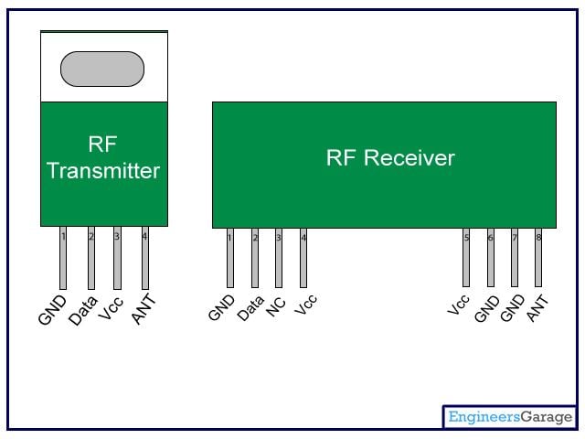
Fig 3 Design description of R.F.I.D module
1. The R.F.I.D. module used in our project is PTR2000.
2. The R.F.I.D. protocol used in our project is to facilitate the proper communication between the on field system and off field system wirelessly which is located within a distance of 100 meters.
3. The R.F.I.D. tag has an integrated circuit employed in it to store and process the average sensed parameter which is the percentage of moisture level in the soil that is calculated through a software program loaded in the on field microcontroller 89c51.
4. The R.F.I.D. reader at the receiver side which is connected to the off field microcontroller 89c51 will read the value stored in the tag which is the average percentage of moisture content in the soil and is given to the off field microcontroller and compared with the set point which is stored in the microcontroller to perform the required control action.
5. It is High Speed - Low Power UHF Data Transceiver Module.
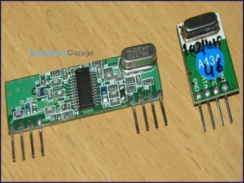
3.6.1 Features of R.F module:
1. 433MHz ISM Band
2. Half Duplex
3. 2 Channel
4. PLL Synthesized
5. Data rate up to 19200bit/s
6. Range : PTR 2000 : 100 meters range line-of-sight in open space
7. Serial Interface Compatible with MCU CMOS
8. No Manchester coding of data required
9. Antenna : PTR 2000 : Loop antenna, on the PCB of the module
10. Single 2.7 to 5.0V Supply
11. Standby Current 8?A
12. Miniature PCB Mounting module
13. Dimensions: PTR 2000 : 40 x 35 x 6mm
Typical Applications of R.F module:
1. MCU to MCU link
2. MCU to PC link
3. Security Applications
4. Vehicle Alarm Systems
5. Remote meter reading
6. Remote data acquisition
7. Alarm and Security System
8. Authorization / Access control
9. Automatic meter reading (AMR)
10. High integrity wireless Fire / Security alarms
11. Wireless Communications
Pin connection for RF sensor
SENSOR CONNECTION
P3.0 RXD Connected to rs232 For debug
P3.1 TXD Connected to rs232 For debug
P3.2 INT0_BAR nIRQ
P3.3 INT1_BAR LED Test led of RF sensor
P3.4 TO SDI
P3.5 T1 nSEL
P3.6 WR_BAR SDO
P3.7 RD_BAR SCK
Sensors
The sensors used in our project are moisture sensors. The architecture of the sensors is as follows.
Moisture Sensor
1. The sensor used is made of plaster of paris, cement and timber.
2. The ratio of the overall mixture of plaster of paris: cement: timber is 2:1:1.
3. The sensor as a whole is buried in the ground with leads outside and sensor buried in inverted position.
4. The outer end which is shown as L1&L2 are conducting leads. These are connected to the network as shown.
5. When sensors are installed at four corners of the field, the buried plaster of Paris sensors will sense the moisture content present in the soil.
6. As the moisture level increases in the block of plaster of Paris the resistance between the two leads (internal part) will decrease, and the conductivity of the leads will increase.
7. As per the research conducted by the members of the project the resistance measured on the DMM that of dry soil is around ‘220K’ and that of wet soil is ‘0 ohms.’
8. Now the other ends are connected to the network to perform conditioning.
9. Similarly outputs from the remaining sensors are obtained which are given to their respective networks to perform conditioning.
It is a device which is basically used to convert the input signal into proper form which is needed to produce the required output. Means it performs the operations like, amplification, attenuation, wave shaping, etc. And here we use the Signal Conditioner as “Amplifier”. We are using LM 324 IC as an Operational Amplifier.
As the moisture level in the soil increases and sensed by the sensing leads, it will reduce the virtual resistance between the two input terminals which leads to completion of the circuit.
Four such networks are employed to obtain the electronic format of the sensed parameters and their respective outputs are given to the respective port pins of the on field microcontroller.
LCD Display
A Liquid crystal display is used to show the heart rate value and the temperature. It is alphanumeric display which can show 16 characters in each lines and it consists of two lines.LCD (Liquid Crystal Display) screen is an electronic display module and find a wide
range of applications.
A 16x2 LCD display is very basic module and is very commonly used in various devices and circuits. These modules are preferred over seven segments and other multi segment LEDs. The reasons being: LCDs are economical; easily programmable; have no limitation of displaying special & even custom characters (unlike in seven segments), animations and so on. A 16x2 LCD means it can display 16 characters per line and there are 2 such lines. In this LCD each character is displayed in 5x7 pixel matrix. This LCD has two registers, namely, Command and Data. The command register stores the command instructions given to the LCD. A command is an instruction given to LCD to do a predefined task like initializing it, clearing its screen, setting the cursor position, controlling display etc. The data register stores the data to be displayed on the LCD.
Power Supply
1. The 230v A.C. mains is given to primary then at the secondary of step down transformer we get 9V 500mA which is the transformer rating used in the project.
2. The output from the transformer is given to the rectifier stage wherein four diodes (1N4007) type is used.
3. The output from there is given to LM 7805 which provides 5V output. .
4. 12V supply is used for relay operation. For that purpose another transformer of 12V/500mA rating is used.
SR NO I/O DEVICE PORT/PIN
Off Field
1 LCD P0
2 RS P2.0
3 RW P2.1
4 EN P2.2
5 Relay For Water pump motor P2.6
6 Relay for Bor Motor P2.7
7 Moisture Level For low P1.4
8 Moisture Level For medium P1.5
9 Moisture Level For high P1.6
10 Buzzer P1.7
11 RF Module (Receiver) P3
ON Field
12 Security Line P1.0
13 CS (pin no.8 of ADC) P1.4
14 DIN (pin no.9 of ADC) MOSI P1.5
15 DOUT (pin no.10 of ADC) MISO P1.6
16 SCLK (pin no.11 of ADC) P1.7
17 RF Module (Transmitter) P3
18 Moisture Sensor o/p to CH0 - CH3 of ADC
20 o/p of LM 35 to op-amp to CH4 of ADC
I/O Configuration:
Mathematical
CALIBRATION FR LM 35 1C->10mV
LM 35 output voltage = 19.1 mvolt
CALIBRATION OF OP-AMP FOR LM35 (TEMP.SENSOR)
Practical Calibration
1) RF = 5.90 kohm
2) R1 = 1 kohm
3) G = ?
G = 1 + RF / R1 Set Value of Gain
= 1 + 5.90 kohm / 1 kohm G = 6.90
= 1 + 5.90 Set Value of RF
G = 6.90 1) RF = 5.90 kohm
Measured Calibration
1) Vo = 1.86 v
2) Vin = 0.292 v
3) G = ?
Calculated Gain by using Measured op amp input output volt i.e Vin & Vo
G = Vo / Vin Calculate Value of Gain
= 1.86 / 0.292 G = 6.37
G = 6.37
Calculate Value of RF
1) G = 6.37 RF = 5.37 kohm
2) R1 = 1 kohm
3) RF = ?
G = 1 + RF / R1
6.37 = 1 + RF / 1 kohm
RF = 5.37 kohm
PCB MANUFACTURING PROCESS
Design
Printed circuit board artwork generation was initially a fully manual process done on clear mylar sheets at a scale of usually 2 or 4 times the desired size. The schematic diagram was first converted into a layout of components pin pads, then traces were routed to provide the required interconnections. Pre-printed non-reproducing mylar grids assisted in layout, and rub-on dry transfers of common arrangements of circuit elements (pads, contact fingers, integrated circuit profiles, and so on) helped standardize the layout. Traces between devices were made with self adhesive tape. The finished layout "artwork" was then photographically reproduced on the resist layers of the blank coated copper-clad boards.
Modern practice is less labor intensive since computers can automatically perform many of the layout steps. The general progression for a commercial printed circuit board design would include:[3]
1. Schematic capture through an electronic design automation tool.
2. Card dimensions and template are decided based on required circuitry and case of the PCB. Determine the fixed components and heat sinks if required.
3. Deciding stack layers of the PCB. 1 to 12 layers or more depending on design complexity. Ground plane and power plane are decided. Signal planes where signals are routed are in top layer as well as internal layers.[4]
4. Line impedance determination using dielectric layer thickness, routing copper thickness and trace-width. Trace separation also taken into account in case of differential signals. Microstrip, stripline or dual stripline can be used to route signals.
5. Placement of the components. Thermal considerations and geometry are taken into account. Vias and lands are marked.
6. Routing the signal traces. For optimal EMI performance high frequency signals are routed in internal layers between power or ground planes as power planes behave as ground for AC.
7. Gerber file generation for manufacturing.
In the design of the PCB artwork, a power plane is the counterpart to the ground plane and behaves as an AC signal ground, while providing DC voltage for powering circuits mounted on the PCB. In electronic design automation (EDA) design tools, power planes (and ground planes) are usually drawn automatically as a negative layer, with clearances or connections to the plane created automatically.
Manufacturers never use the Gerber or Exelon files directly on their equipment, but always read them into their CAM system. PCBs cannot be manufactured professionally without CAM system. The PCB CAM system performs the following functions:
1. Input of the Gerber data
2. Verify the data; optionally DFM
3. Compensate for deviations in the manufacturing processes (e.g. scaling to compensate for distortions during lamination)
4. Panelize
5. Output of the digital tools (layer images, drill files, AOI data, electrical test files)
4.2 Penalization:
Penalization is a procedure used to handle PCBs which would otherwise be too small to process. A number of identical circuits are printed onto a larger board (the panel) which can then be handled in the normal way. The panel is broken apart into individual PCBs when all other processing is complete. Separating the individual PCBs is frequently aided by drilling or routing perforations along the boundaries of the individual circuits, much like a sheet of postage stamps. Another method, which takes less space, is to cut V-shaped grooves across the full dimension of the panel. The individual PCBs can then be broken apart along this line of weakness.[7]
4.3 Copper patterning:
The pattern in the manufacturers PCB CAM system is usually output on a photo mask (photo-tool, film) by a photo plotter and replicated via silk screen printing or by exposing on a photo-sensitive photo resist coating. Direct imaging techniques are sometimes used for high-resolution requirements. Subtractive, additive and semi-additive processes
4.4 Plating and coating
PCBs are plated with solder, tin, or gold over nickel as a resist for etching away the unneeded underlying copper
After PCBs are etched and then rinsed with water, the solder mask is applied, and then any exposed copper is coated with solder, nickel/gold, or some other anti-corrosion coating. Matte solder is usually fused to provide a better bonding surface or stripped to bare copper. Treatments, such as benzimidazolethiol, prevent surface oxidation of bare copper. The places to which components will be mounted are typically plated, because untreated bare copper oxidizes quickly, and therefore is not readily solderable. Traditionally, any exposed copper was coated with solder by hot air solder leveling.The HASL finish prevents oxidation from the underlying copper, thereby guaranteeing a solderable surface.This solder was a tin-lead alloy, however new solder compounds are now used to achieve compliance with the RoHS directive in the EU and US, which restricts the use of lead. One of these lead-free compounds is SN100CL, made up of 99.3% tin, 0.7% copper, 0.05% nickel, and a nominal of 60ppm germanium.
It is important to use solder compatible with both the PCB and the parts used. An example is Ball Grid Array (BGA) using tin-lead solder balls for connections losing their balls on bare copper traces or using lead-free solder paste.
Other platings used are OSP (organic surface protectant), immersion silver (IAg), immersion tin, electroless nickel with immersion gold coating (ENIG), electroless nickel electroless palladium immersion gold (ENEPIG) and direct gold plating (over nickel). Edge connectors, placed along one edge of some boards, are often nickel plated then gold plated. Another coating consideration is rapid diffusion of coating metal into Tin solder. Tin forms intermetallics such as Cu5Sn6 and Ag3Cu that dissolve into the Tin liquidus or solidus(@50C), stripping surface coating or leaving voids.
Electrochemical migration (ECM) is the growth of conductive metal filaments on or in a printed circuit board (PCB) under the influence of a DC voltage bias.Silver, zinc, and aluminum are known to grow whiskers under the influence of an electric field. Silver also grows conducting surface paths in the presence of halide and other ions, making it a poor choice for electronics use. Tin will grow "whiskers" due to tension in the plated surface. Tin-Lead or Solder plating also grows whiskers, only reduced by the percentage Tin replaced. Reflow to melt solder or tin plate to relieve surface stress lowers whisker incidence. Another coating issue is tin pest, the transformation of tin to a powdery allotrope at low temperature.
4.5 Solder resist application
Areas that should not be soldered may be covered with solder resist (solder mask). One of the most common solder resists used today is called LPI (liquid photoimageable). A photo sensitive coating is applied to the surface of the PWB, then exposed to light through the solder mask image film, and finally developed where the unexposed areas are washed away. Dry film solder mask is similar to the dry film used to image the PWB for plating or etching. After being laminated to the PWB surface it is imaged and develop as LPI. Once common but no longer commonly used because of its low accuracy and resolution is to screen print epoxy ink. Solder resist also provides protection from the environment.
PCB Manufacturing Process
The two processing methods used to produce a double-sided PWB with plated through holes.
Subtractive methods remove copper from an entirely copper-coated board to leave only the desired copper pattern
Silk screen printing uses etch-resistant inks to protect the copper foil. Subsequent etching removes the unwanted copper. Alternatively, the ink may be conductive, printed on a blank (non-conductive) board. The latter technique is also used in the manufacture of hybrid circuits.
1. Photoengraving uses a photo mask and developer to selectively remove a photo resist coating. The remaining photo resist protects the copper foil. Subsequent etching removes the unwanted copper.
2. PCB milling uses a two or three-axis mechanical milling system to mill away the copper foil from the substrate. A PCB milling machine (referred to as a PCB Prototypes) operates in a similar way to a plotter, receiving commands from the host software that control the position of the milling head in the x, y, and (if relevant) z axis. Data to drive the Prototypes is extracted from files generated in PCB design software and stored in HPGL or Gerber file format.
In additive methods the pattern is electroplated onto a bare substrate using a complex process. The advantage of the additive method is that less material is needed and less waste is produced. In the full additive process the bare laminate is covered with a photosensitive film which is imaged (exposed to light though a mask and then developed which removes the unexposed film). The exposed areas are sensitized in a chemical bath, usually containing palladium and similar to that used for through hole plating which makes the exposed area capable of bonding metal ions. The laminate is then plated with copper in the sensitized areas. When the mask is stripped, the PCB is finished.
Semi-additive is the most common process: The unpatterned board has a thin layer of copper already on it. A reverse mask is then applied. (Unlike a subtractive process mask, this mask exposes those parts of the substrate that will eventually become the traces.) Additional copper is then plated onto the board in the unmasked areas; copper may be plated to any desired weight. Tin-lead or other surface plating’s are then applied. The mask is stripped away and a brief etching step removes the now-exposed bare original copper laminate from the board, isolating the individual traces. Some single-sided boards which have plated-through holes are made in this way. General Electric made consumer radio sets in the late 1960s using additive boards.The (semi-)additive process is commonly used for multi-layer boards as it facilitates the plating-through of the holes to produce conductive vias in the circuit board.
TESTING AND TROUBLSHOOTING
COLD TEST:
1. The first step was to carry out the visual inspection of the PCB. This means to check any short or cut in the tracks on PCB. Find any missing pads if any where found on it. We did mechanical repair of the same.
2. The second step involved the continuity testing. This means to check that the current is flowing through all the tracks.
3. Thirdly testing solder of socket crystal & reset circuitry.
TEST RESULT:
1. Give VCC and GND to microcontroller.
2. Check voltage between 18 & 19 pins (XTAL 1, XTAL 2). It should be 2.5.
3. Check available voltage pin 3.0-1.4. If all these voltage are coming then the microcontroller is working properly.
4. Check VCC and GND of LCD & write a RTN for display any message on LCD if the message does not come check the supply again also check the data lines for any opens or short.
MICROCONTROLLER TESTING:
Initially the µC is given the power supply. All the respective ports and port pins were checked when the signals were proper, it means that all the µC signal were correct. If these signals are not proper, we can check the signals from VCC ground, reset, circuit respectively.
Even after the above test if the signals are not proper it means that the purchased CPU is not functioning properly & must be thrown.
1. We can put latch and memory in their respective sockets we wrote a small program for the same then checked for numbers on port pin For the transmission of data stored in memory of µC. Various parameters of communication port such as parity, data type baud rate were checked before the transmission
2. Accepting the data next step was to check that all the devices that are connected and the program that was written to accept the data from the µC is successful or not then the further modifications were done in the program.
TESTING A RESISTOR
To check the value of a resistor, it should be removed from the circuit. The surrounding components can affect the reading and make it lower.Resistors VERY RARELY change value, but if it is overheated or damaged, the resistance can increase. You can take the reading of a resistor "in-circuit" in one direction then the other, as the surrounding components may have diodes and this will alter the reading. You can also test a resistor by feeling its temperature-rise. It is getting too hot if you cannot hold your finger on it (some "metal film" resistors are designed to tolerate quite high temperatures).
RESISTOR NETWORKS
To reduce the number of resistors in a circuit, some engineers use a set of identical resistors in a package called a Single-In-Line (SIL) resistor network. It is made with many resistors of the same value, all in one package. One end of each resistor is connected all the other resistors and this is the common pin, identified as pin 1 and has a dot on the package.These packages are very reliable but to make sure all the resistors are as stated, you need to locate
TESTING POTENTIOMETERS (variable resistors)
To check the value of a variable resistor, it should be removed from circuit or at least 2 legs should be removed. A Rheostat is a variable resistor using only one end and the middle connected to a circuit. The resistance between the two outside pins is the value marked on the component and the centre leg will change from nearly zero to the full resistance as the shaft is rotated."Pots" generally suffer from "crackle" when turned and this can be fixed by spraying up the shaft and into the pot via the shaft with a tube fixed to a can of "spray-lubricant" (contact cleaner). "Pre-set pots" and "trim pots" are miniature versions of a potentiometer and they are all tested the same
FOCUS POTS
Focus pots quite often get a spot of dirt where the wiper touches the track. Cleaning with spray fixes the bad focus but if the pot is leaking to chassis from inside the pot (due to the high voltage on the terminals) simply remove it from the chassis and leave it floating (this will restore the high voltage to the picture tube) or you can use one from an old chassis.
TESTING FUSES, LEADS AND WIRES
All these components come under the heading TESTING for CONTINUITY. Turn off all power to the equipment before testing for shorts and continuity. Use the low resistance"Ohms Scale" or CONTINUITY range on your multimeter. All fuses, leads and wires should have a low, very low or zero resistance. This proves they are working.
A BLOWN FUSE
The appearance of a fuse after it has "blown" can tell you a lot about the fault in the circuit. If the inside of the glass tube (of the fuse) is totally blackened, the fuse has been damaged very quickly. This indicates a very high current has passed through the fuse.
Depending on the rating of the fuse, (current rating) you will be able to look for components that can pass a high current when damaged - such as high power transistors, FETs, coils, electrolytics. Before re-connecting the supply, you should test the "SUPPLY RAILS" for resistance. This is done by measuring them on a low OHMs range in one direction then reverse the leads to see if the resistance is low in the other direction.
A reading can be very low at the start because electrolytics need time to charge-up and if t
he reading gradually increases, the power rail does not have a short. An overload can occur when the supply voltage rises to nearly full voltage, so you sometimes have to fit a fuse and see how long it takes to "blow."If the fuse is just slightly damaged, you will need to read the next part of this eBook, to see how and why this happens:
FAST AND SLOW BLOW FUSES
There are many different sizes, shapes and ratings of a fuse. They are all current ratings as a fuse does not have a voltage rating. Some fuses are designed for cars as they fit into the special fuse holders. A fuse can be designed for 50mA, 100mA, 250mA, 315mA, 500mA, 1Amp, 1.5amp, 2amp, 3amp, 3.15amp 5amp, 10amp, 15amp, 20amp, 25amp, 30amp, 35amp, 50amp and higher. Some fuses are fast-blow and some are slow-blow.
A "normal" fuse consists of a length of thin wire. Or it may be a loop of wire that is thin near the middle of the fuse. This is the section that will "burn-out."A "normal" fuse is a fast-blow fuse. For instance, a 1amp fuse will remain intact when up to 1.25 amp flows. When a circuit is turned on, it may take 2-3 amps for a very short period of time and a normal 1 amp fuse will get very hot and the wire will stretch but not "burn-out." You can see the wire move when the supply turns on.
If the current increases to 2amps, the fuse will still remain intact. It needs about 3 amp to heat up the wire to red-hot and burn out. If the current increases to 5 amp, the wire VOLATILISES (burns-out) and deposits carbon-black on the inside of the glass tube.A slow-blow fuse uses a slightly thicker piece of wire and the fuse is made of two pieces of wire joined in the middle with a dob of low-temperature solder. Sometimes one of the pieces of wire is a spring and when the current rises to 2.5 amp, the heat generated in the wire melts the solder and the two pieces of wire "spring apart." A slow-blow fuse will allow a higher current-surge to pass through the fuse and the wire will not heat up and sag. Thus the fuse is not gradually being damaged and it will remain in a perfect state for a long period of time. A fuse does not protect electronic equipment from failing. It acts AFTER the equipment has failed. It will then protect a power supply from delivering a high current to a circuit that has failed. If a slow-blow fuse has melted the solder, it could be due to a slight overload, slight weakening of the fuse over a period of time or the current-rating may be too low. You can try another fuse to see what happens. You can replace a fast-acting fuse (normal fuse) with a slow blow if the fast-acting fuse has been replaced a few times due to deterioration when the equipment is turned on. But you cannot replace a slow-blow fuse with a fast acting fuse as it will be damaged slightly each time the equipment is turned on and eventually fail.
TESTING COILS, INDUCTORS and YOKES
Coils inductors and yokes are just an extension of a length of wire. The wire may be wrapped around a core made of iron or ferrite. It is labeled "L" on a circuit board. You can test this component for continuity between the ends of the winding and also make sure there is no continuity between the winding and the core. The winding can be less than one ohm, or greater than 100 ohms, however a coil of wire is also called an INDUCTOR and it might look like a very simple component, but it can operate in a very complex way. The way it works is a discussion for another eBook. It is important to understand the turns are insulated but a slight fracture in the insulation can cause two turns to touch each other and this is called a "SHORTED TURN" or you can say the inductor has "SHORTED TURNS."
When this happens, the inductor allows the circuit to draw MORE CURRENT. This causes the fuse to "blow."The quickest way to check an inductor is to replace it, but if you want to measure the inductance, you can use an INDUCTANCE METER. You can then compare the inductance with a known good component. An inductor with a shorted turn will have a very low or zero inductance, however you may not be able to detect the fault when it is not working in a circuit as the fault may be created by a high voltage generated between two of the turns. Faulty yokes (both horizontal and vertical windings) can cause he picture to reduce in size and/or bend or produce a single horizontal line. A TV or monitor screen is the best piece of Test Equipment as it has identified the fault. It is pointless trying to test the windings further as you will not be able to test them under full operating conditions.
MEASURING AND TESTING INDUCTOR:
Inductors are measured with an INDUCTANCE METER but the value of some inductors is very small and some Inductance Meters do not give an accurate reading.
The solution is to measure a larger inductor and note the reading. Now put the two inductors in SERIES and the values ADD UP - just like resistors in SERIES. This way you can measure very small inductors. VERY CLEVER!
TESTING SWITCHES & RELAYS
Switches and relays have contacts that open and close mechanically and you can test them for CONTINUITY. However these components can become intermittent due to dirt or pitting of the surface of the contacts due to arcing as the switch is opened.
It is best to test these items when the operating voltage and current is present as they quite often fail due to the arcing. A switch can work 49 times then fail on each 50th operation. The same with a relay. It can fail one time in 50 due to CONTACT WEAR.
If the contacts do not touch each other with a large amount of force and with a large amount of the metal touching, the current flowing through the contacts will create HEAT and this will damage the metal and sometimes reduce the pressure holding the contact together.
This causes more arcing and eventually the switch heats up and starts to burn. Switches are the biggest causes of fire in electrical equipment and households.
A relay also has a set of contacts that can cause problems. There are many different types
of relays and basically they can be put into two groups.
1. An electromagnetic relay is a switch operated by magnetic force. This force is generated by current through a coil. The relay opens and closes a set of contacts.
The contacts allow a current to flow and this current can damage the contacts. Connect 5v or 12v to the coil (or 24v) and listen for the "click" of the points closing. Measure the resistance across the points to see if they are closing. You really need to put a load on the points to see if they are clean and can carry a current. The coil will work in either direction. If not, the relay is possibly a CMOS relay or Solid State relay.
2. An electronic relay (Solid State Relay) does not have a winding. It works on the principle of an opto-coupler and uses a LED and Light Activated SCR or Opto-TRIAC to produce a low resistance on the output. The two pins that energise the relay (the two input pins) must be connected to 5v (or 12v) around the correct way as the voltage is driving a LED (with series resistor). The LED illuminates and activates a light-sensitive device
TESTING A CAPACITOR
There are two things you can test with a multimeter:
1. A short-circuit within the capacitor
2. Capacitor values above 1µ
You can test capacitors in-circuit for short-circuits. Use the x1 ohms range. To test a capacitor for leakage, you need to remove it or at least one lead must be removed. Use the x10k range on an analogue or digital multimeter. For values above 1u you can determine if he capacitor is charging by using an analogue meter. The needle will initially move across the scale to indicate the cap is charging, then go to "no deflection." Any permanent deflection of the needle will indicate leakage. You can reverse the probes to see if the needle moves in the opposite direction. This indicates it has been charged. Values below 1u will not respond to charging and the needle will not deflect. This does not work with a digital meter as the resistance range does not output any current and the electrolytic does not charge.
Rather than spending money on a capacitance meter, it is cheaper to replace any suspect capacitor or electrolytic. Capacitors can produce very unusual faults and no piece of test equipment is going to detect the problem. In most cases, it is a simple matter to solder another capacitor across the suspect component and view or listen to the result. This saves all the worry of removing the component and testing it with equipment that cannot possibly give you an accurate reading when the full voltage and current is not present. It is complete madness to even think of testing critical components such as capacitors, with TEST EQUIPMENT. You are fooling yourself. If the Test Equipment says the component is ok, you will look somewhere else and waste a lot of time.
FINDING THE VALUE OF A CAPACITOR
If you want to find the value of a surface-mount capacitor or one where the markings have been removed, you will need a CAPACITANCE METER. Here is a simple circuit that can be added to your meter to read capacitor values from 10p to 10u.
REPLACING A CAPACITOR
Always replace a capacitor with the exact same type. A capacitor may be slightly important in a circuit or it might be extremely critical. A manufacturer may have taken years to select the right type of capacitor due to previous failures. A capacitor just doesnt have a "value of capacitance."It may also has an effect called "tightening of the rails." In other words, a capacitor has the ability to react quickly and either absorb or deliver energy to prevent spikes or fluctuations on the rail. This is due to the way it is constructed. Some capacitors are simply plates of metal film while others are wound in a coil. Some capacitors are large while others are small. They all react differently when the voltage fluctuates. Not only this, but some capacitors are very stable and all these features go into the decision for the type of capacitor to use.
6.16 TESTING DIODES
1. Diodes can have 4 different fauly
2. Open circuit in both directions
3. Low resistance in both directions
4. Leaky
5. Breakdown under load.
TESTING A DIODE ON AN ANALOGUE METER
Testing a diode with an Analogue Multimeter can be done on any of the resistance ranges. [The high resistance range is best - it sometimes has a high voltage battery for this range but this does not affect our testing] There are two things you must remember.
When the diode is measured in one direction, the needle will not move at all. The technical term for this is the diode is reverse biased. It will not allow any current to flow. Thus the needle will not move.
When the diode is connected around the other way, the needle will swing to the right (move up scale) to about 80% of the scale. This position represents the voltage drop across the junction of the diode and is NOT a resistance value. If you change the resistance range, the needle will move to a slightly different position due to the resistances inside the meter. The technical term for this is the diode is forward biased. This indicates the diode is not faulty.The needle will swing to a slightly different position for a "normal diode" compared to a Schottky diode. This is due to the different junction voltage drops. However we are only testing the diode at very low voltage and it may break-down when fitted to a circuit due to a higher voltage being present or due to a high current flowing.
The leads of an Analogue Multimeter have the positive of the battery connected to the black probe and the readings of a "good diode"
ADVANTAGES
1. High water application efficiency.
2. Ability to irrigate irregular shaped fields.
3. Allows safe use of recycled water.
4. This makes increase in productivity
5. Minimized soil erosion.
6. Highly uniform distribution of water i.e., controlled by output of each nozzle.
7. Lower labor cost.
8. Man power reduces.
9. Improves crop yields
10. This is very useful to all climatic conditions any it is economic friendly.
DISADVANTAGES
1. Short range of RF Module ,but this can be overcome by using long range RFID,Reapeter or GSM technology
2. As compared to Conventional Irrigation system equipments are costlier.
APPLICATIONS
1. For agriculture purpose
2. In domestic application
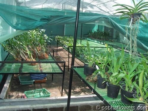
3. In green house
4. Gardening
CONCLUSION
1. Here we are conclude that our Indian agriculture based on Embedded & Wireless Technology.
2. In the interest of promoting sustainability in agriculture we has developed a methodology of irrigation scheduling and a low cost technology to implement the methodology
3. The results shows that the reduction in the amount of water applied can be achieved without significant reductions in yield
4. The reductions in nutrient losses could provide a grower with the means to reduce application amounts and thus costs, and more importantly reduce the risk of surrounding water resources to nutrient contamination.
5. This is critical to the sustainability of agriculture in INDIA and many other areas of the world, where increasing population and public environmental awareness introduces a fierce competition for water resources.
FUTURE SCOPE
1. In future we will used GSM module for communication between On Field & Off Field. (Range of Wireless data transmission will be increase )
2. In future if you modify it properly then this system can also supply agricultural chemicals like calcium, sodium,ammonium, zinc to the field along with Fertilizers with adding new sensors and valves.
If you’re not using drip irrigation in your garden, now’s the time to start. Drip irrigation is a highly efficient way to water, so it saves you time and helps to conserve precious supplies of clean water. Studies show that well-designed drip systems use at least 30 percent, and in some cases 50 percent, less water than other methods of watering such as sprinkling
A drip irrigation system delivers water directly to the root zone of a plant, where it seeps slowly into the soil one drop at a time. Almost no water is lost through surface runoff or evaporation, and soil particles have plenty of opportunity to absorb and hold water for plants. It also means very few nutrients leach down beyond the reach of plant roots. Furthermore, since drip irrigation delivers water directly to the plants you want to grow, less is wasted on weeds. The soil surface between the plants also remains drier, which discourages weed seeds from sprouting.
For busy gardeners, the main benefit of drip irrigation is the savings of both time and effort. Drip systems eliminate the need to drag around hoses and sprinklers. For systems that use a timer, gardeners need only spend a few seconds to turn the system on; the timer automatically turns it off
Plants watered with drip systems grow more quickly and are more productive, because they have all the water they need and their growth isn’t slowed by water stress. (This is especially true when drip irrigation is used in conjunction with mulch.) Also, plants watered by drip irrigation don’t end up with wet foliage from a sprinkler spray, and that can help prevent some foliage diseases such as powdery mildew.
Start with Soaker Hoses
The easiest way to experiment with drip irrigation is to buy a couple of soaker hoses. These hoses ooze water over their entire length. You simply position a soaker on the soil surface next to the plants you want to water, and then connect the open end of the hose to your garden hose and turn on the water supply. You can move the hose from one bed to another in your garden, or buy several and leave them in place. Soaker hoses can be used for short runs (100 to 200 feet) over flat surfaces