
Characteristic Symbols Particle velocity v, SVL Sound intensity I, SIL | Sound pressure p, SPL Particle displacement δ Sound power P, SWL | |
 | ||
Transmission loss (TL) in duct acoustics, together with insertion loss (IL), describes the acoustic performances of a muffler like system. It is frequently used in the industry areas such as muffler manufacturers and NVH department of automobile manufacturers. Generally the higher transmission loss of a system it has, the better it will perform in terms of noise cancellation.
Contents
Introduction
Transmission loss (TL) (more specifically in duct acoustics) is defined as the difference between the power incident on a duct acoustic device (muffler) and that transmitted downstream into an anechoic termination. Transmission loss is independent of the source and presumes (or requires) an anechoic termination at the downstream end.
Transmission loss does not involve the source impedance and the radiation impedance inasmuch as it represents the difference between incident acoustic energy and that transmitted into an anechoic environment. Being made independent of the terminations, TL finds favor with researchers who are sometimes interested in finding the acoustic transmission behavior of an element or a set of elements in isolation of the terminations. But measurement of the incident wave in a standing wave acoustic field requires uses of impedance tube technology, may be quite laborious, unless one makes use of the two-microphone method with modern instrumentation.
Mathematical definition
By definition the TL on an acoustic component, for example a muffler, is described as:
where:
Note that
And in most muffler applications, Si and So, the area of the exhaust pipe and tail pipe, are generally made equal, thus we have:
Thus, TL equals 20 times the logarithm (to the base 10) of the ratio of the acoustic pressure associated with the incident wave (in the exhaust pipe) and that of the transmitted wave (in the tail pipe), with the two pipes having the same cross-sectional area and the tail pipe terminating anechoically. However this anechoic condition is normally difficult to meet under practical industry environment, thus it is usually more convenient for the muffler manufacturers to measure insertions loss during their muffler performance tests under working conditions (mounted on an engine).
Also, since the transmitted sound power cannot possibly exceed the incident sound power (or
Transmission matrix description
The low-frequency approximation implies that each subsystem is an acoustic two-port (or four-pole system) with two (and only two) unknown parameters, the complex amplitudes of two interfering waves travelling in opposite directions. Such a system can be described by its transmission matrix (or four-pole matrix), as follows
where
where:
A simple example
Considering we have the most simplest reactive silencer with only one expansion chamber (length l and cross-sectional area S2), with inlet and outlet both having cross-sectional area S1). As we know the transmission matrix of a tube (in this case, the expansion chamber) is
Substitute to the equation of TL above, it can be seen that the TL of this simple reactive silencer is
where
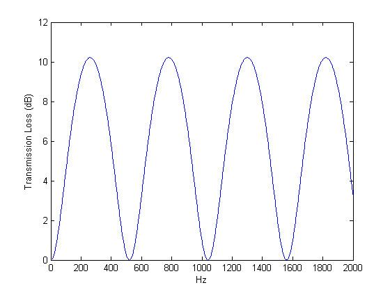
As a simple example, consider a one chamber silencer with h=S1/S2=1/3, at around 400 °C the sound speed is about 520 m/s, with l=0.5 m, one easily calculate the TL result shown on the plot on the right. Note that the TL equals zero when frequency is a multiple of
Also note that the above calculation is only valid for low-frequency range because at low-frequency range the sound wave can be treated as a plane wave. The TL calculation will start losing its accuracy when the frequency goes above the cutoff frequency, which can be calculated as