
 | ||
Simulation Of Transformer performance on loading:
Brief Introduction:
A transformer is a static electrical machine which performs the task of energy transformer from one electrical circuit to another electrical circuit through a magnetic circuit without change in frequency. It operates on ac only. It works on the principle of mutual induction. The main parts of a transformer are: windings, cores, insulating material, bushings and cooling arrangements.
As far as its function is concerned, it is generally used to step-up or step-down the voltage which really helps in reducing the transmission losses.
Modeling of Transformer
A model is designed to simulate the performance of a single-phase transformer under different loads. It is done after considering the appropriate mathematical equations governing the performance of transformer. Generally transformer performance is usually characterized by its efficiency and voltage regulation which varies with the magnitude and pahse of the load.
Before discussing the simulation model, let’s have a look at some basic equations governing the function of a transformer (two winding transformer is considered here).
Since both the primary and secondary windings are made of copper, the windings contribute to the ohmic losses and leakage flux which is represented by resistance and leakage reactance in the primary and secondary circuit.
Mathematical model of transformer can be derived from its equivalent circuit
Equations governing the performance of transformer i.e. efficiency are
Efficiency (%) = (Output power)—/(input power) X 100 or (output power)/(output power+losses) X 100
Input power= V1*I1;
Output Power=V2*I 2*cos Ф;
Losses=Ohmic losses (Copper losses) + Iron losses (Constant losses) =(I2^2)*Re + Pi.
Notations:
V1=Primary voltage
V2= secondary voltage
I1, I2 = primary and secondary currents
R1 and R2 = primary and secondary winding resistance
a= turns ratio=N1/N2
Re= equivalent resistance referred to secondary = R2+ (R1/a2)
Efficiency (%) = (V2*I 2*cos Ф)/(V2*I2*cosФ+I2^2*Re+Pi )
MATLAB SIMULATION OF TRANSFORMER
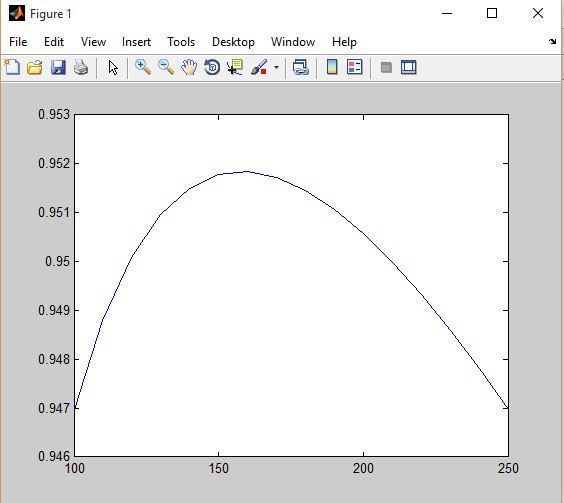
The variation of efficiency with loading of transformer is simulated using MATLAB.
Let’s assume a transformer of the following characteristics
Re+jXe=5+8i, a=0.5; V1=250V; 50 Hz; Zl=100 to 250 ohms with steps of 10; Pi(Constant losses)=40W
CONCLUSION
It is seen that efficiency is low at small loads and reaches a maximum value for a certain load. The efficiency then decreases as the load increased. Sometimes it is desired to know under what conditions and at which value of the load, the transformer will operate at its maximum efficiency. By analyzing the curve or mathematical proof it shows that the efficiency for a given power factor is maximum when copper losses are equal to the constant losses.