Puneet Varma (Editor)

Schering Bridge

Updated on
Edit
Like
Comment
Share on FacebookTweet on TwitterShare on LinkedInShare on Reddit
Schering Bridge

The Schering Bridge is an electrical circuit used for measuring the insulating properties of electrical cables and equipment. It is an AC bridge circuit, developed by Harald Schering. It has the advantage that the balance equation is independent of frequency.

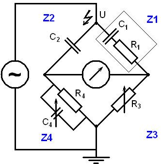
The connections of the Schering bridge under balance conditions are shown in the figure below.

In this diagram:

  • C1 = capacitor whose capacitance is to be determined,
  • R1 = a series resistance representing the loss in the capacitor C1,
  • C2 = a standard capacitor,
  • R3 = a non-inductive resistance,
  • C4 = a variable capacitor,
  • R4 = a variable non-inductive resistance in parallel with the variable capacitor C4.
  • References

    Schering Bridge Wikipedia