
 | ||
A reliability block diagram (RBD) is a diagrammatic method for showing how component reliability contributes to the success or failure of a complex system. RBD is also known as a dependence diagram (DD).
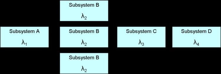
A RBD or DD is drawn as a series of blocks connected in parallel or series configuration. Each block represents a component of the system with a failure rate. Parallel paths are redundant, meaning that all of the parallel paths must fail for the parallel network to fail. By contrast, any failure along a series path causes the entire series path to fail.
An RBD may be drawn using switches in place of blocks, where a closed switch represents a working component and an open switch represents a failed component. If a path may be found through the network of switches from beginning to end, the system still works.
An RBD may be converted to a success tree by replacing series paths with AND gates and parallel paths with OR gates. A success tree may then be converted to a fault tree by applying de Morgan's theorem.
In order to evaluate RBD, closed form solution are available in the case of statistical independence among blocks or components. In the case the statistical independence assumption is not satisfied, specific formalisms and solution tools, such as dynamic RBD, have to be considered.