
 | ||
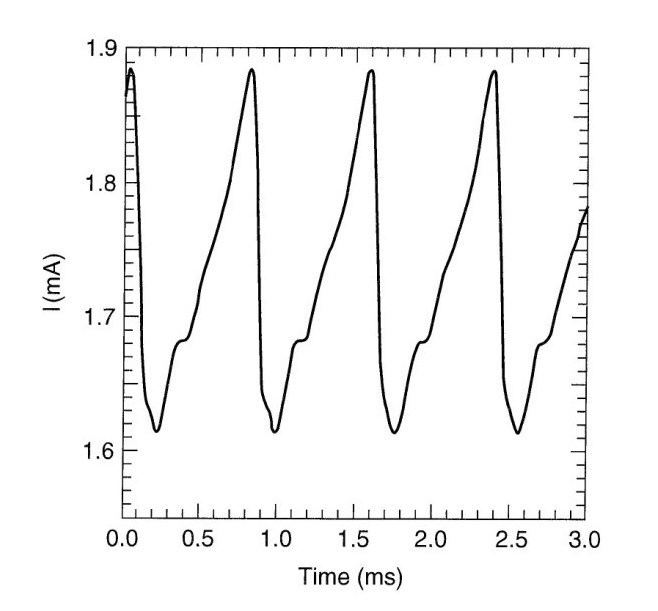
A high-field domain is a band of elevated field orthogonal to the equi-current lines and seen in photoconductive CdS and monochromatic light at the band edge as dark band was discovered by Böer, using the Franz-Keldysh effect. Such domains must appear whenever the conductivity decreases stronger than linearly. This can be caused by the field dependence of the carrier density, as observed in copper-doped CdS caused by Frenkel Poole excitation of holes, causing faster electron recombination, known as field quenching. These high-field domains, now referred to as Böer domains, or by field dependence of the mobility, caused by excitation of electrons into higher conduction bands with lower mobility as observed in GaAs, called the Gunn effect. The high-field domains can be identified by periodical field oscillations between high (the domain) and low values, as shown in Fig. 1.
Many other crystals show such domains by typical current oscillations. The high-field domains in copper doped CdS can be easily observed by the Franz-Keldysh effect as stationary, adjacent to the cathode or moving. These are analyzed as another example below.
Theory: Stationary high-field domains can be analyzed from the transport- and Poisson equations:
The projection of any solution curves into an arbitrary nF plane can be filled with direction arrows at any point of this plane. Two auxiliary curves for which dn/dx = 0, called n2(F) and dF/dx = 0 called n1(F) divide this plane into four quadrants with the same type of directions. This is shown in Fig. 2(left) in a double logarithmic representation. Any solution of an n-type semiconductor with blocking cathode must start at the boundary density nc that is below the density in the bulk, and approaches the singular point at which dn/dx = dF/dx = 0, that is in the bulk where both n(x) and F(x) are constant. The solution curve represents a Schottky-blocking contact as shown in Fig. 2(B), curve (a).
When n(x) decreases at higher fields due to field-quenching cause by Poole-Frenkel excitation of holes from Coulomb attractive hole traps, that consequently enhances electron recombination through recombination centers, and thereby deforms the n1(x) curve at higher fields as shown in Fig. 2(B). When the bias is increased the current curve n2(x) is shifted upwards and to the right, and when it crosses n1(x) again, it produces a second singular point II. With further increased bias this singular point II reaches the value of the boundary density nc, and the solution curve changes from a monotonic increasing Schottky-solution, to a high-field domain, curve (b): that remains constant near the cathode, and then changes within a few Debye lengths to approach the constant value in the bulk, near the singular point I. The width of the domain increases with bias (Fig. 3a), while the current remains constant (Fig. 3c). The domain is visible as dark part in the transmission picture through the CdS platelett, extending from the cathode as shown in Fig. 3a. The field in the domain can be obtained from the slope of the domain that increases with bias (Fig. 3b).
When, with further increased bias the domain fills the entire sample,then it flips to an anode adjacent high-field domain (Fig. 4b). The field at the cathode is now much higher than for the cathode adjacent domain (Fig. 4b and c), while the current still remains essentially constant (Fig. 4c).
High-field domains to determine the work function of blocking contacts
Since the high field domain starts at the electron density given by the work-function at the cathode and pulls the Schottky barrier open to a constant field in the domain, this work function can be determined precisely, and it can be used as a tool to determine the changes of the work function, as it varies depending on external parameters. As an example, it can be shown that it depends on the optical excitation in a photoconductor (See Fig. 5).
High-field domains as tools to measure the electron density in the field quenched branch and of the electron mobility as a function of the temperature
The high-field domain is determined by the boundary density at the cathode and the field within the domain. A shadow band in front of the cathode acts as a pseudo-cathode, as it reduces the electron density within the shadow (Fig. 6). This can be used as an experimental tool to change the boundary density as a function of the light intensity within the shadow.
This permits to measure directly the electron density in the field-quenched range, using different pseudo-electron densities, causing a shift of the singular point, and measuring the domain field.
The electron Hall mobility can be measured by placing the CdS platelett in a magnet and applying a bias sufficient to create a high-field domain. When the domain is extended to include the Hall electrodes one can determine the Hall mobility within the domain. Different fields in the high-field domain are achieved by using different samples or different cathode metals.
Stationary domains to explain efficiency improvement of CdTe solar cells with a thin CdS cover layer
The application of a 200Å thick copper doped layer of CdS on top of a typically 2 μm thick CdTe solar cell, increases the open circuit voltage substantially, so that it can reach the theoretical limit of the band gap of the CdTe-emitter when extrapolated to 0 K. This improvement can be explained by limiting the field in the CdS side of the junction when it reaches the critical value for a high-field domain to appear and thereby limits the maximum junction field to the domain field of typical 50 kV/cm. This field is below a field in which electron leaking from the CdS into CdTe occurs, resulting in an increase of the open circuit voltage and thereby an increase of the solar cell conversion efficiency.
Moving high-field domains in copper-doped CdS with a small circular cathode
The domains started from the cathode, separates and, with increasing bias increases its radius. When the anode is reached the ring disappeared and a new domain grows from the cathode. The process repeated itself with a period of 10 sec (Fig. 7).
Such undeformed moving domains in crystals with slit electrodes are bands parallel to the electrodes, and seen by the oscillating field, when plotted in a x,F,t diagram give the optical impression of bifurcation (Fig. 8).
Such moving high-field domains are measured in p-Ge with (a) local voltage (b) field- and (c) carrier density oscillation (Fig. 9).
Undeformed moving high-field domains and domains with deformation (Chaos) are observed in many other crystals, and also in nanocrystals or superlatices. However, because of the small size they can only be analyzed by the changing shape of the current-voltage characteristics.
Böer domains
The high-field domains were renamed Böer domains at the 50th anniversary of their discovery.
The Benefits of the High-Field Domains
Copper-doped photoconductive CdS shows high-field domains when at sufficient bias and with blocking contacts these domains remain attached to the contacts. The field within the domain is constant and the current is by drift only. With increased bias the domain width increases. When it reaches both electrodes the entire crystal becomes space-charge free (this is one more example at which an interaction vanishes: for the interaction of electrons with phonons, superconductivity results; from the interaction of photons with phonons, lasers can be produced). This gives the opportunity to measure the spectral distribution of defect levels free of interaction of the broadening electric field surrounding the defects. A first example is shown by the extremely sharp quenching spectrum of a CdS crystal that has been inverted to become p-type with a high-field-domain (Fig. 10)
Another benefit of the high-field domain is the direct connection of any p-type emitter through a copper-doped thin CdS layer directly to an electron-blocking electrode through which the holes are extracted, and the open circuit voltage is increased to approach the theoretical limit of the band gap or the emitter at 0K. Because in the CdS the hole current is now carried by drift only, we can finally draw the band model of a typical solar cell. e.g. the CdS/CdTe cell as given in Fig. 11. For the first time we can replace the estimate of the band connection of abrupt hetero-junctions from the difference of electron affinities by calculating it from the continuity of the majority carrier current, with the only small discontinuity left by the difference of the effective masses of the carriers at the different carrier bands.