
 | ||
The critical load is the maximum load which a column can bear while staying straight. It is given by the formula:
Contents
- Assumptions of the model
- Mathematical Derivation Pin Ended Column
- Mathematical Derivation General Approach
- References
where
This formula was derived in 1757, by the Swiss mathematician Leonhard Euler. The column will remain straight for loads less than the critical load. The "critical load" is the greatest load that will not cause lateral deflection (buckling). For loads greater than the critical load, the column will deflect laterally. The critical load puts the column in a state of unstable equilibrium. A load beyond the critical which causes the column to fail by buckling. As the load is increased beyond the critical load the lateral deflections increase, until it may fail in other modes such as yielding of the material. Loading of columns beyond the critical load are not addressed in this article.
Around 1900, J. B. Johnson showed that at high slenderness ratios an alternative formula should be used.
Assumptions of the model
The following assumptions are made while deriving Euler’s formula:
- The material of the column is homogeneous and isotropic.
- The compressive load on the column is axial only.
- The column is free from initial stress.
- The weight of the column is neglected.
- The column is initially straight (no eccentricity of the axial load).
- Pin joints are friction-less (no moment constraint) and fixed ends are rigid (no rotation deflection).
- The cross-section of the column is uniform throughout its length.
- The direct stress is very small as compared to the bending stress (the material is compresses only within the elastic range of strains).
- The length of the column is very large as compared to the cross-sectional dimensions of the column.
- The column fails only by buckling. This is true if the compressive stress in the column does not exceed the yield strength
σ y
σ = P c r A = π 2 E ( L e / r ) 2 < σ y
Where:
Mathematical Derivation - Pin Ended Column
The following model applies to columns simply supported at each end (
Firstly, we will put attention to the fact there are no reactions in the hinged ends, so we also have no shear force in any cross-section of the column. The reason for no reactions can be obtained from symmetry (so the reactions should be in the same direction) and from moment equilibrium (so the reactions should be in opposite directions).
Using the free body diagram in the right side of figure 3, and making a summation of moments about point A:
where w is the lateral deflection.
According to Euler–Bernoulli beam theory, the deflection of a beam is related with its bending moment by:
so:
Let
We get a classical homogeneous second-order ordinary differential equation.
The general solutions of this equation is:
If
However, from the other solution
Together with
and depending upon the value of
Theoretically, any buckling mode is possible, but in the case of a slowly applied load only the first modal shape is likely to be produced.
The critical load of Euler for a pin ended column is therefore:
and the obtained shape of the buckled column in the first mode is:
Mathematical Derivation - General Approach
The differential equation of the axis of a beam is:
For a column with axial load only, the lateral load
This is a homogeneous fourth-order differential equation and its general solution is
The four constants
- Pinned end:
w = 0 andM = 0 → d 2 w d x 2 = 0 - Fixed end:
w = 0 andd w d x = 0 - Free end:
M = 0 → d 2 w d x 2 = 0 andV = 0 → d 3 w d x 3 + λ 2 d w d x = 0
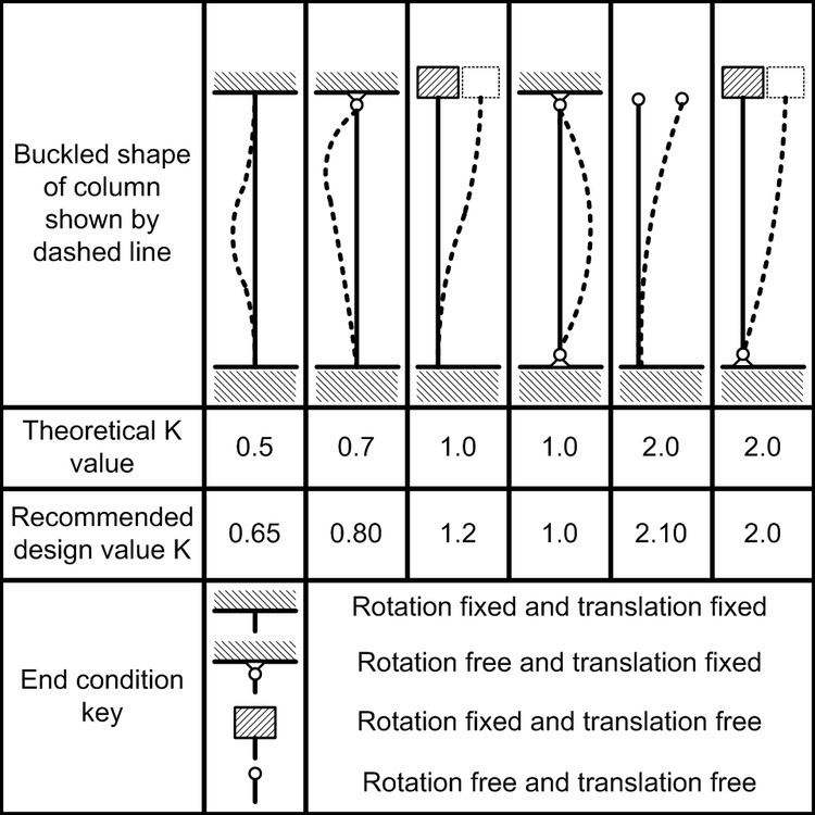
Using each time a different combination of these BCs, eigenvalue problems are obtained. Solving those, we get the values of Euler's critical load for each one of the cases presented in Figure 1.