Trisha Shetty (Editor)

Ellipse Law

Updated on
Edit
Like
Comment
Share on FacebookTweet on TwitterShare on LinkedInShare on Reddit
Ellipse Law

The Law of the Ellipse, or Stodola's cone law, provides a method for calculating the highly nonlinear dependence of extraction pressures with a flow for multistage turbine with high backpressure, when the turbine nozzles are not choked. It is important in turbine off-design calculations.

Description

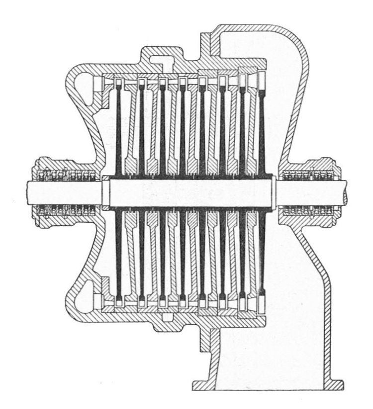
We consider a multistage turbine, like in the picture. The design calculation is done for design flow rate ( m ˙ 0 , the flow expected for the most uptime). The other parameters for design are the temperature and pressure at the stage group intake, T 0 and p 0 , respectively the extraction pressure at the stage group outlet p 2 (the symbol p 1 is used for the pressure after a stage nozzles, pressure does not interfere in relations here).

For off-design calculations, the off-design flow rate is m ˙ 01 , respectively the temperature and pressure at the stage group intake are T 01 and p 01 and the outlet pressure is p 21 .

Stodola established experimentally that the relationship between these three parameters represented in Cartesian coordinate system has the shape of a degenerate quadric surface, the cone directrix being an ellipse. For a constant initial pressure p 01 the flow rate depends on the outlet pressure p 21 as an arc of ellipse in a plane parallel to m ˙ 01 0 p 21

For very low outlet pressure p 21 , like for condensing turbines, flow rates do not change with the outlet pressure, but drops very quickly with the increase of the backpressure. For a given outlet pressure p 21 , flow rates changes depending on the inlet pressure p 01 as an arc of hyperbola in a plane parallel to m ˙ 01 0 p 01 .

Usually, Stodola's cone do not represent absolute flow rates and pressures, but relative to the maximum flow rate and pressures, the maximum values of the diagram having in this case the value of 1. The maximum flow rate has the symbol m ˙ 0 m and the maximum pressures at the inlet and outlet have the symbols p 0 m and p 2 m . The pressure ratios for design flow rate at the intake and outlet are ϵ 0 = p 0 / p 0 m and ϵ 2 = p 2 / p 2 m , and the off-design ratios are ϵ 01 = p 01 / p 0 m and ϵ 21 = p 21 / p 2 m .

If the speed of sound is reached in a stage, the group of stages can be analyzed till that stage, which is the last in the group, the remaining stages forming another group of analysis. This division is imposed by the stage working in limited (choked) mode. The cone is shifted in the 0 p 02 axis direction, appearing a triangular surface, depending on the critical pressure ratio ϵ c = p c / p 01 , where p c is the outlet critical pressure of the stage group.

The analytical expression of the flow ratio is:

m ˙ 0 m ˙ 01 = T 01 T 0 ϵ 0 2 ( 1 ϵ c ) 2 ( ϵ 2 ϵ c ϵ 0 ) 2 ϵ 01 2 ( 1 ϵ c ) 2 ( ϵ 21 ϵ c ϵ 01 ) 2

For condensing turbine the ratio ϵ c is very low, previous relation reduces to:

m ˙ 0 m ˙ 01 = T 01 T 0 ϵ 0 2 ϵ 2 2 ϵ 01 2 ϵ 21 2

simplified relationship obtained theoretically by Gustav Flügel (1885–1967).

In the event that the variation of inlet temperature is low, the relationship is simplified:

m ˙ 0 m ˙ 01 = ϵ 0 2 ϵ 2 2 ϵ 01 2 ϵ 21 2

For condensing turbines ϵ 2 ϵ 21 0 , so in this case:

m ˙ 0 m ˙ 01 = ϵ 0 ϵ 01 = p 0 p 01

During operation, the above relations allow the assessment of the flow rate depending on the operating pressure of a stage.

References

Ellipse Law Wikipedia