
 | ||
The automatic warning system (AWS) is a form of limited cab signalling introduced in 1956 in the United Kingdom.
Contents
- Principles of operation
- AWS at signals
- Early devices
- GWR automatic train control
- StrowgerHudd system
- Network Rail
- Expansion of AWS application
- Disadvantages
- Bi directional operation
- Liberia
- Other countries
- References
The Rail Safety and Standards Board defines it as:
The original concept of AWS was to provide the driver with an audible and visual indication of whether the distant signal was clear or at caution. Should the driver fail to respond to a warning indication, an emergency brake application will be initiated.
Since the introduction of multi-aspect signalling, the majority of signals are fitted with AWS.
It was based on a 1930 system developed by Alfred Ernest Hudd and marketed as the "Strowger-Hudd" system. An earlier contact system, installed on the Great Western Railway since 1906 and known as automatic train control (ATC), was gradually supplanted by AWS within the Western Region of British Railways.
Principles of operation
AWS is part of the signalling system and warns the driver whether the next signal is clear or not. These warnings are usually given 200 yards (180 metres) before the signal, though the distance can vary according to linespeed. Information about the signal aspect is conveyed by electromagnetic induction to the moving train through equipment fixed in the middle of the track, known as an AWS magnet. The system works by the train detecting sequences and polarities of magnetic fields passing between the track equipment and the train equipment via a receiver under the train.
The equipment on a train consists of;
AWS at signals
As the train passes over an AWS magnet, the 'sunflower' indicator in the driver's cab will change to all black. If the signal being approached is displaying a 'clear' for a semaphore or green for a multiple aspect colour light signal, the AWS will sound a bell (modern locomotives/multiple units use an electronic sounder that gives a distinctive 'ping') and leave the visual indicator black. This lets the driver know that the next signal is showing 'clear' and that the AWS system is working.
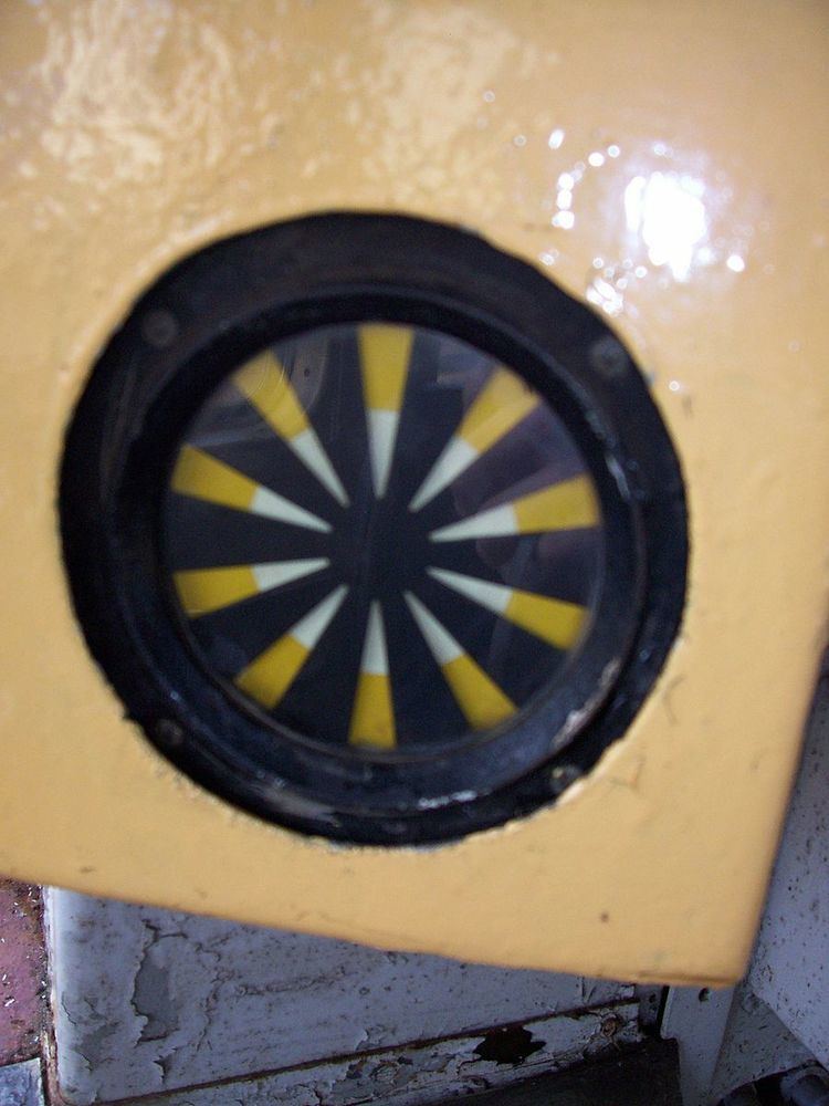
If the signal being approached is displaying a restrictive aspect (red, yellow or double yellow in colour-light installations or a distant semaphore at caution (horizontal)), the AWS will sound a horn. The driver then has approximately 2 seconds to press the AWS/TPWS acknowledgement button. The horn then stops and the visual indicator changes to a pattern of black and yellow spokes, which persists until the next AWS magnet and reminds the driver that they have cancelled the AWS. As a fail-safe mechanism, the button must be released after it has been pressed. If a driver should collapse onto the button or keep it held down, the AWS will not be cancelled.
If the driver fails to cancel the warning in time the emergency brake will apply and bring the train to a stand. When this occurs the red Brake demand light will flash on the AWS/TPWS Driver machine interface. The driver must now push the AWS/TPWS acknowledgement button, and the brakes will release after a safety time out period has elapsed.
AWS is provided at most main aspect signals on running lines, though there are some exceptions:
Early devices
Early devices used a mechanical connection between the signal and the locomotive. In 1840, the locomotive engineer Edward Bury experimented with a system whereby a lever at track level, connected to the signal, sounded the locomotive's whistle and turned a cab-mounted red lamp. Ten years later, the redoubtable Colonel William Yolland of the Railway Inspectorate was calling for a system that not only alerted the driver but also automatically applied the brakes when signals were passed at danger but no satisfactory method of bringing this about was found.
In 1873, United Kingdom Patent No. 3286 was granted to C. Davidson and C.D. Williams for a system in which, if a signal was passed at danger, a trackside lever operated the locomotive's whistle, applied the brake, shut off steam and alerted the guard. Numerous similar patents followed but they all bore the same disadvantage – that they could not be used at higher speeds for risk of damage to the mechanism – and they came to nothing. In Germany, the Kofler system used arms projecting from signal posts to connect with a pair of levers, one representing caution and the other stop, mounted on the locomotive cab roof. To address the problem of operation at speed, the sprung mounting for the levers was connected directly to the locomotive's axle box to ensure correct alignment. When Berlin's S-Bahn was electrified in 1929, a development of this system, with the contact levers moved from the roofs to the sides of the trains, was installed at the same time.
The first useful device was invented by Vincent Raven of the North Eastern Railway in 1895, patent number 23384. Although this provided audible warning only, it did indicate to the driver when points ahead were set for a diverging route. By 1909, the company had installed it on about 100 miles of track. In 1907 Frank Wyatt Prentice patented a radio signalling system, using a continuous cable laid between the rails to relay "Hertzian Waves" to the locomotive. The signal was turned off if the block were not "clear", a white or green light in the cab then turned to red and the brakes were applied. The LSWR installed the system on its Hampton Court Branch in 1911, but shortly after removed it when the line was electrified.
GWR automatic train control
The first system to be put into wide use was developed in 1905 by the Great Western Railway and protected by UK patents 12661 and 25955. Its benefits over previous systems were that it could be used at high speed and that it sounded a confirmation in the cab when a signal was passed at clear.
In the final version of the GWR system, the locomotives were fitted with a solenoid-operated valve into the vacuum train pipe, maintained in the closed position by a battery. At each distant signal, a long ramp was placed between the rails. This ramp consisted of a straight metal blade set edge-on, almost parallel to the direction of travel (the blade was slightly offset from parallel so in its fixed position it would not wear a groove into the locomotives' contact shoes), mounted on a wooden support. As the locomotive passed over the ramp, a sprung contact shoe beneath the locomotive was lifted and the battery current holding closed the brake valve was broken. In the case of a clear signal, current from a battery energising the ramp (but at opposite polarity) passed to the locomotive through the contact and maintained the brake valve in the closed position, with the reversed-polarity current ringing a bell in the cab. When the signal was at 'danger', the ramp battery was disconnected and so could not replace the locomotive's battery current: the brake valve solenoid would then be released and a horn sounded in the cab. The driver was then expected to cancel the warning and apply the brakes under his own control.
Notwithstanding the heavy commitment of maintaining the batteries in the locomotives and signal boxes, the GWR installed the equipment on all its main lines. For many years, Western Region (successors to the GWR) locomotives were dual fitted with both GWR ATC and BR AWS system.
Strowger–Hudd system
By the 1930s, other railway companies, under pressure from the Ministry of Transport, were considering systems of their own. A non-contact method based on magnetic induction was preferred, to eliminate the problems caused by snowfall and day-to-day wear of the contacts which had been discovered in existing systems. The Strowger-Hudd system of Alfred Hudd, which used a pair of magnets, one a permanent and one an electro-magnet, was tested by the Southern Railway, London and North Eastern Railway and the London, Midland and Scottish Railway but these trials came to nothing.
In 1948 Hudd, now working for the LMS, equipped the London, Tilbury and Southend line, a division of the LMS, with his system. It was successful and British Railways developed the mechanism further by providing a visual indication in the cab of the aspect of the last signal passed. In 1956, the Ministry of Transport evaluated the GWR, LTS and BR systems and selected the one developed by BR as standard for Britain's railways. This was in response to the Harrow and Wealdstone accident in 1952.
Network Rail
Network Rail (NR) AWS consists of:
The system works on a set/reset principle.
When the signal is at 'clear' or green ("off"), the electro-magnet is energised. As the train passes, the permanent magnet sets the system. A short time later, as the train moves forward, the electromagnet resets the system. Once so reset, a bell is sounded (a chime on newer stock) and the indicator is set to all black if it is not already so. No acknowledgement is required from the driver. The system must be reset within one second of being set, otherwise it behaves as for a caution indication.
An additional safeguard is included in the distant-signal control wiring to ensure the AWS "clear" indication is only given when the distant is proved "off" – mechanical semaphore distants have a contact in the electromagnet coil circuit closed only when the arm is raised by at least 40 degrees, whilst colour-light distants have a sensing relay in the DR (green) filament circuit, and the newest type of single-aperture LED main signal unit has a "Green-Proved" output from its driver electronics that is used to enable the electromagnet via the SSI.
When the distant signal is at 'caution' or yellow (on), the electro-magnet is de-energised. As the train passes, the permanent magnet sets the system. However, since the electro-magnet is de-energised, the system is not reset. After the one-second delay within which the system can be reset, a horn warning is given until the driver acknowledges by pressing a plunger. If the driver fails to acknowledge the warning within 2.75 seconds, the brakes are automatically applied. If the driver does acknowledge the warning, the indicator disk changes to yellow and black, to remind the driver that he has acknowledged a warning. The yellow and black indication persists until the next signal and serves as a reminder between signals that the driver is proceeding under caution. The one-second delay before the horn sounds allows the system to operate correctly down to speeds as low as 1.75 miles per hour. Below this speed, the caution horn warning will always be given, but it will be automatically cancelled when the electromagnet resets the system if the driver has not already done so. The display will indicate all black once the system resets.
The system is fail-safe since, in the event of a loss of power, only the electro-magnet is affected and therefore all trains passing will receive a warning. The system suffers one drawback in that on single track lines, the track equipment will set the AWS system on a train travelling in the opposite direction from that for which the track equipment is intended but not reset it as the electromagnet is encountered before the permanent magnet. To overcome this, a suppressor magnet may be installed in place of an ordinary permanent magnet. When energised, its suppressing coil diverts the magnetic flux from the permanent magnet so that no warning is received on the train. The suppressor magnet is fail-safe since loss of power will cause it to act like an ordinary permanent magnet. A cheaper alternative is the installation of a lineside sign that notifies the driver to cancel and ignore the warning. This sign is a blue square board with a white St Andrew's cross on it (or a yellow board with a black cross, if provided in conjunction with a temporary speed restriction).
With mechanical signalling, the AWS system was installed only at distant signals but, with multi-aspect signalling, it is fitted at all main line signals. All signal aspects, except green, cause the horn to sound and the indicator disc to change to yellow on black.
AWS equipment without electromagnets are fitted at locations where a caution signal is invariably required or where a temporary caution is needed (for example, a temporary speed restriction). This is a secondary advantage of the system because temporary AWS equipment need only contain a permanent magnet. No electrical connection or supply is needed. In this case, the caution indication in the cab will persist until the next green signal is encountered.
Expansion of AWS application
Disadvantages
Because it was developed before multiple-aspect signalling became widespread, AWS can only indicate whether a signal is "Green" or "not Green". Even though a multiple-aspect signal can display three or four aspects, AWS has only two states.
AWS is an advisory system and can be easily overridden by habituated reactions of the driver, especially when they are proceeding at speed under continuous yellow aspects. This has led to a number of fatal accidents.
Also, there is no compulsory stop when a red signal is passed. The newer TPWS, which is installed at certain stop signals, the approach to reductions of permissible speed of more than a third and buffer stops, overcomes this problem.
Bi-directional operation
Because the permanent magnet is located in the centre of the track, it operates in both directions. The permanent magnet can be suppressed by an electric coil of suitable strength.
Where signals applying to opposing directions of travel on the same line are suitably positioned relative to each other, a common magnet may be used, comprising an unsuppressed permanent magnet associated with both signals' electro-magnets.
Liberia
One of the mining railways in this country had a more advanced AWS system that employed two or three magnets of either polarity and located near the rails to avoid the suppression problem. The system was therefore able to give more aspects than the BR version.
Other countries
The BR AWS system is also used in: