
 | ||
Amtrak operates a 60 Hz Traction power system along the Northeast Corridor between New Haven, Connecticut and Boston, Massachusetts. This system was built in the late 1990s and supplies locomotives with power from an overhead catenary system at 25 kV, 60 Hz. The system is also commonly known as the Northend Electrification, in contrast to the Southend Electrification that runs from New York City to Washington DC.
Contents
System architecture
The basic system unit is an Elementary Electrical Section consisting of a segment of one or more parallel tracks, each with a contiguous contact (or catenary or trolley) wire for the locomotive pantograph and an electrically separate feed wire. Elementary electrical sections are separated by section breaks where the contact and feeder wires can be interrupted with motor-operated air switches to isolate a section in the event of a fault or to permit maintenance.
An Electrical Section is a collection of elementary electrical sections, section breaks, air switches and paralleling stations between a Substation and a Switching Station.
At each substation, utility supplied single phase power is transformed and injected into the two electrical sections terminating at that substation. There are eight electrical sections in the system, two for each substation. The substations drive the contact and feed wires in a split phase arrangement so that each wire is at 25 kV with respect to the grounded running rails with 50 kV between them.
At periodically spaced Paralleling Stations within each electrical section the tracks' catenary wires are connected together to one side of an autotransformer and the feeder wires are connected together to the other side of the autotransformer. The autotransformer center-tap is connected to the grounded running rails that return the current from the locomotives. The paralleling stations thus reduce voltage drops by feeding a locomotive from both directions along its contact wire and spreading the load across all the contact and feed wires of a multitrack system. The split-phase arrangement also gains the increased efficiency of operating at 50 kV while the highest voltage with respect to ground remains only 25 kV. (The same split-phase method is used in North American homes to supply high power loads such as air conditioners with the efficiency of a 240 V supply while retaining the safety advantages of a 120 V supply.)
Substations
There are four Substations between New Haven and Boston:
Each station contains two 115 kV (single phase) to 50 kV (single phase with center tap) transformers to convert the utility supplied transmission voltage to 50kV traction voltage. Output circuit breakers, and a capacitor based filter network are installed. The filter banks suppress the high frequency (that is anything above 60 Hz) harmonics on the catenary lines generated by locomotives' solid-state traction motor inverters. The filters also provide reactive power support and correct for power factor. Amtrak's 60 Hz electrification distributes power using ±25 kV from ground via a center tap of the 115/50 kV transformers. This system is also known as 2 x 25 kV.
Switching stations
Three Switching Stations are located along the line which separate the different electrical sections (power zones):
The switching stations contain three autotransformers similar to the paralleling stations (which have one), and also have additional circuit breakers to allow segmentation of catenary and cross-connection between power zones.
Electrical sections encompass both tracks between a substation and the adjacent switching stations. Normally no power flows from one side of a switching station to the other side; it is like two adjacent paralleling stations which serve different electrical sections. In the event that a substation is taken out of service, switching stations have additional circuit breakers which allow feeding an electrical section from the adjacent section.
Since switching stations, like substations, normally separate electrical sections with different supply sources (and thus different phase or voltage), a neutral section always occupies the track between the two electrical sections.
In the event of a fault in one elementary electrical section, the switching station can 'back-feed' the far portion of the affected track from the non-affected track, which the supplying substation feeds the near end.
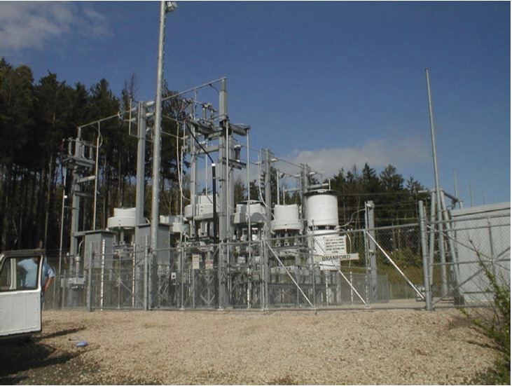
Paralleling stations
Eighteen Paralleling Stations are located at approximately six mile intervals along the line. Each contains a single autotransformer (with the exception of Roxbury, which has two), automatic circuit breakers, motor-operated air switches, and a control shed. The autotransformers are rated at 10 MVA, 1.2% impedance, two winding, 27.5 kV.
Each paralleling station bus is connected to both north and south track catenary and feeder lines via automatic circuit breakers. The autotransformer is connected to the bus bars by an additional circuit breaker. The track breakers at the paralleling stations trip on sensing no-voltage. Thus when a line fault causes the supplying substation breakers to trip, the paralleling stations also trip. This action separates the two tracks from one another electrically and allows the substation to automatically restore one of the tracks (the non-faulted one). After a variable time delay (to reduce simultaneous inrush current), over-voltage relays will re-shut the track circuit breakers on the non-faulted track.