
Power type Electric UIC class Bo-Bo-Bo | Build date 1940–1962 Wheel diameter 1.250 m (49.21 in) | |
 | ||
Builder Breda, OM CGE, OM Reggiane, Marelli, SNOS Savigliano, FIAT, TIBB, OF Pistoiesi, Ansaldo Gauge 1,435 mm (4 ft 8 ⁄2 in) standard gauge | ||
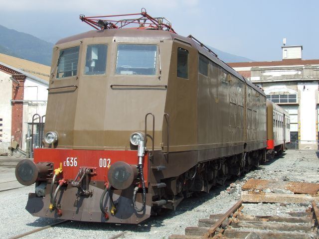
The FS E.636 is a class of Italian articulated electric locomotives. They were introduced in the course of the 1940s until the 1960s, and have been decommissioned since 2006. They have been one of the most numerous Italian locomotive group, and have been widely employed during their long career, hauling every type of train, ranging from freight to long range passenger services. Their introduction also saw the employment of some revolutionary (for the time) design concepts, such as the articulated carbody and the three bogies scheme.
Contents
History
The E.636 was designed to overcome the problems showed in the 1930s by both the E.626 multi-purpose and E.326 high-speed locomotives, in order to better handle the increasing railway traffic in Italy.
The E.636 was the first Italian locomotive adopting the Bo-Bo-Bo configuration with chassis divided into two articulated parts pivoting on the central bogie, which is very well suited for the often tortuous lines of Italy and that would have been later repeated on the E.645/646 and [[FS Class E. 656|E.656]] classes. The presence of a great number of wheels was considered important due to the presence of a number of high-slope lines in the Italian railroad network as it increases the adhesion limit, meaning that the locomotive is less prone to wheel slips. The new engines weighted approximately 101 short tons (90 long tons; 92 t). Engines were initially the same as E.626. The 32R used a 3 kV catenary but this was soon shown to be inadequate and so were updated and provided with a new hollow axle transmission system. Mainly two different gear ratios were installed: 21/65 for sloping lines or heavy freight trains (maximum speed of 95 km/h (59 mph), elevated later to 110 km/h), and the longer 28/65, with a maximum speed of 120 km/h (75 mph), suited for passenger services.
The locomotive was built in three different series:
The first unit entered service in May 1940. Six locomotives were destroyed during World War II. After the war the total number of locomotives was brought to 469, also thanks to the support from the Marshall Plan, and making it one of the most numerous groups of Italian locomotives. All the units were painted with an auburn livery; this was changed in the 1990s to a white one with green stripes for most trains (XMPR livery).
By 2000s railway standards, E.636s were old and uncomfortable. The original design of the cockpits proved absolutely unfit to modern safety standards: this was shown in an accident in 1996 at Sulmona, where the engine driver died despite the low speed, without being able to leave the cockpit in time. 200 units were therefore rebuilt and stripped of all asbestos.
Starting from the 1990s, E.636s were used mainly for cargo services, save for the more backlog Sicilian lines. Some units were lent to minor Italian railroads. The phasing out of the entire class was completed in May 2006.
Technical details
E.636 are very simple locomotives. Most functions of the main command circuit are accomplished through various relays and contactors. In case of failure the train driver could easily fix them to at least free the tracks; also, especially in last years of their service, E.636s were the first locomotives that the new train drivers studied during their training courses, due to their simple working mechanics.
Motors and electrical description
As most older Italian locomotives, E.636 has a rheostat (formed by 16 cast iron resistors connected in series, for a total resistance of 29 ohms) that needs to be gradually, but as soon as possible, excluded on start-ups, which regulates the current to the six 32R-200 DC traction motors, two per bogie.
The motors can be connected in three combinations: series, series-parallel and parallel; each combination provides a progressively higher voltage to the motors, therefore increasing the current.
Their set-up is the following:
The rheostat (connected in series to the traction motors) is necessary because the DC motor has the intrinsic characteristic of absorbing a current inversely proportional to its rotating speed; at high speeds, it absorbs less current. This means that on start the current would be very high, because the only resistance encountered would be only the one offered by motors and internal conductors, which is very low (a short circuit, in practice). The rheostat increases the overall resistance when starting the locomotive, lowering the current and allowing a smoother start.
In S-P and P combinations, the rheostat is divided in three branches connected in parallel; this lowers the overall rheostat equivalent resistance to about 3.5 ohm, while in S combination its elements are all connected in series.
Like almost every Italian locomotive with rheostatic regulation since E.626, traction is controlled via a lever (commonly referred to as maniglione) mounted on a support called roncola; this support has several notches, each representing a portion of the rheostat, plus three "end combination" notches and two "transition" positions (a bigger block between the notches). To accelerate, the driver rotates gradually counterclockwise the lever notch by notch, and in doing so the various rheostat contactors are closed, shunting the resistors and lowering the total rheostat resistance, also allowing more current to the motors; as speed builds up, the counter-electromotive force lowers this current, until the rheostat is no longer necessary: it is, then, totally excluded (obviously if in traction and in an "end combination" notch). This safely allows traction for an indefinite period of time, within certain limits.
When the end combination notches are reached, the driver can then insert the single shunt (one for each combination) or make a transition to the next combination, reintroducing the rheostat which has to be excluded again, for the following combinations until the end of the parallel combination is reached. The shunts increase the current into the motors by shunting some motor spires (through a contactor in parallel); this reduces the magnetic flux and, as said, increases the current (since the two are inversely proportional). There are various "shunt levels", depending on the locomotive, as is further explained; usually, there is one per combination. It is also important to remove the shunts before making a transition, in order to avoid flashes due to abnormally high currents.
Like some E.626s, E.636 locomotives are not provided with the "CEM" motor combiner (CEM stands for Combinatore Escluditore Motori), a device that, during transitions, rotates, combining the motors accordingly through various contactors.
On E.636, this is achieved through the uses of more delicate spires, so transitions (especially backward ones) need to be very slow and gradual. The optimal moment to pass to the following/preceding combination first/last notches is when the motor ammeter indicates 0 Ampères, which happens when passing over the transition position with the lever (the driver should briefly stop in the middle of the block and pay attention to the ammeter), meaning that the motor contactors are in optimal position and is safe to proceed. Failure in doing this may result in flashes that will damage the contactors.
An important parameter the driver has to consider, especially during rheostatic exclusion, is the current into the traction circuit.
In particular, if he is excluding too fast, a wheel slippage can occur (in this case the use of sanders and reducing throttle can help), and one or more maximum current relays can open when the maximum allowed current value is exceeded.
The locomotive is protected from overly high currents through different kinds of relays:
When they open, they also open the main breaker; that cuts the connection to the catenary.
Before the 1970s, the maximum currents for the relays were the following:
Between 1970 and 1980, the previous values changed:
As can be seen, the currents allowed in series are 450 A in both cases, while in Series-Parallel and Parallel combinations are 350 A and 450 A respectively.
As said, one level of field shunt (percentage of field weakening: 31%) is allowed in each combination; however, some units received 92-250 (used on FS Class E.424) and 32RT-200 type motors which allowed a maximum of 5 levels of field shunts (percentage of field weakening: 65%, 45% on the latters). These units were later made identical to standard ones again.
Motion transmission
Units from 001 to 243 mounted Negri-type transmission, except for units 195-198 and 176-183 which had a rubber tampons in place of coil packs and double hollow axle transmission and rubber tampons respectively.
All the following built units had the same transmission type of 176-183 but slightly different.
Different locomotives have received various gear ratios (see "Special Units" for more details):
Auxiliary and pneumatic services
The motor cooling-fans were activated by two 4.5 kW 3,000 V dedicated motors until unit 201; later units have 1 kW motors identical to the ones used on FS Class E646; they are also used as dynamos to recharge the 24 V batteries (only if line voltage is greater than 1,500 V) used to feed low tension devices (lights, locomotive heating systems, contactors etc.)
Air production on the locomotive was granted by two C38 type compressors; later they were upgraded with the more reliable W242, however, on some units, only one compressor was replaced, leaving one of each type in use on a single locomotive; the C38 produced air until 8 bars in main reservoir tanks were reached, while the W242 from 8 to 9 bars. In fact, on these units, only the W242 was used on normal conditions; the other one only if pressure dropped below 7 bars.
Main-tanks and the 24 V batteries supplies air and current to several systems:
Originally the locomotive mounted a 7-position L-type Westinghouse brake controller and wheel-type locomotive brake, later replaced by the more common Oerlikon FV4 and RA-M2 levers respectively.
Braking systems
The locomotive has three kinds of brakes:
It is a negative-type brake and is called continuous because it extends itself through the entire train, automatic because if brake continuity is no longer present (general pipe breaks), emergency braking is automatically applied.
On units with Breda-type valves and Oerlikon levers the brakes are graduable during braking and releasing; the working principles are the following.
The braking system of the locomotive is formed by an array of components:
When brakes are released, pressure in the brake pipe is about 5 bar (500 kPa; 73 psi), and 0 bar (0 kPa; 0 psi) in brake cylinders.
To brake the train the driver, by moving the brake controller, creates a depression in a particular tank called "bariletto", which, through a series of coils creates a connection to the exterior which makes the general pipe to gradually lower its pressure to a value equal to the one present in the aforementioned tank (how fast this happens depends on train length: the longer it is, the slower this procedure will be). Inside the distributore the command reservoir pressure "wins" over now lower pipe pressure and thus the piston moves, creating a connection between the braking cylinders and the auxiliary reservoir (fed by the main tanks), which will then send a quantity of air to the brake cylinders proportional to the entity of the depression. The maximum pressure that can be reached into the brake cylinders on E636 is 3.8 bar (380 kPa; 55 psi), which corresponds to a pressure inside the general pipe of about 3.5 bar (350 kPa; 51 psi).
In case of emergency braking, the brake pipe is put to direct communication with outside atmosphere, rapidly dropping pressure, and consequently making the train brake very fastly (though there isn't a variation of braking power: only the braking speed is affected).
To release brakes, the driver makes the pressure rise in the bariletto, via the brake controller; the pressure in the brake pipe is restored (air is taken from the main reservoir tanks, and from the main pipe if present) to the value present in the bariletto. Inside the ditributore the brake pipe pressure wins over the command reservoir pressure and so the connection between the brake cylinders and the auxiliary tanks is modified (or cut, depending on the pipe pressure); the brake cylinders unload themselves sending their air outside until their pressure reaches a value proportional to the entity of the depression. When pipe pressure is 5 bar (500 kPa; 73 psi), the cylinders will unload until they are empty.
For a faster brakes' release, it is also possible to briefly "overload" the braking system to a pressure proportional to the depression previously present, up to a maximum pressure of 7.2 bar (720 kPa; 104 psi); shortly after this, the pressure drops to 5.5 bar (550 kPa; 80 psi), and is gradually brought back to 5 bar (500 kPa; 73 psi) in about 240 secs.
However, on units with Triple Valves (Distributore tipo Westinghouse) and 7-position levers, braking circuit is slightly different. The distributore is divided in two parts like said before, but there isn't the command reservoir tank: when the pressure inside the brake pipe drops, it's directly the auxiliary reservoir that makes the frame put in the middle moving. Braking is not gradual on release in this case: when the driver puts the controller on "release" position, brakes are fully released; if he brakes again too shortly after, there is the risk to have a loss of braking power because there may not be enough air to brake optimally, since the absence of the fixed pressure of the command reservoir doesn't ensure that there is enough air to safely release the brakes. It is even possible to fully exhaust the reservoir, with the consequent danger to not be able to stop the train at all. This is prevented in units with Breda and other types of valves as the brakes cannot be fully released if there is not enough air in main reservoir tanks to brake again.
There is a risk associated to the "overload" operation. Inside the distributore the pressures inside the two chambers are balanced: during the overload both command reservoir and brake pipe pressures rise proportionally. As said they are gradually lowered back to 5 bar (500 kPa; 73 psi) but it may happen that the command reservoir "gets struck" to a higher pressure, while the pipe pressure is lower. This keeps the connection between the auxiliary reservoir and the brake cylinders and consequently the brakes in effect. In this occurrence a possible solution is to overload again the system so pressures can be rebalanced, or, if this doesn't work, to manually "reset" the command reservoir (emptying it) by pulling a lever located outside. On units with seven-position levers the risk is greater: the pipe is put to direct connection with the main tanks and, if the controller is left for too much time in the overload position, it may reach a very high pressure (even 9 bar or 900 kPa or 130 psi). It is very easy for the brakes to remain in effect in this case, and the only practicable solution is to manually empty the command reservoir tanks as said above.
Mechanical modifications
The locomotive is formed by two half carbodies, pivoting over the central bogie. Between them, there is a bellows, which was originally made with rubber then replaced in the 1950s by an impermeable membrane. In recent years this was further replaced by flexible plastic material.
On post war units, 7 mm (0.28 in) reinforcement frames have been introduced on the chassis and under the cabs, as the first 108 units showed some mechanical weaknesses in those points; in the mid-1980s it was decided to reinforce only the chassis on pre-war units (however units 026 an 065 never received these modifications).
To reduce parasite motion, dampers were mounted between the carbodies: glycerine-type from units 1-276 and special-oil type from unit 277 onwards, although these were later eliminated in 1977 because considered useless.
The first 108 units had different rheostat ventilation shafts on the roof than the rest of the units ones, although these were later replaced with the more efficient shafts used on the latter units.
They also had sliding oil-buckles, while following units had rolling bearing ones.
Units 162-171 were equipped with French-derived Athermos buckles for testing purposes, which were later removed.
Sandthrowers were mounted internally into the bogie in the units 001 - 108; after the war they were replaced by external ones that also were natively mounted on later units.
Safety systems
The first 108 locomotives originally had mounted a vigilance pedal designed by FS engineer Minucciani, that required a periodic acknowledgement from the driver when the train was moving (or emergency braking would have been commanded), but after the war, due to labor union pressures, it was discontinued; however, starting from the 1970s, many (not all) units received "Ripetizione Segnali a 4 codici" system, Hasler speedometer and a modified "speed graph recorder" (Zona tachigrafica), that also recorded the codes received from the RS.
Special and experimental units
During the 1960s-1970s Ansaldo-Breda built a locomotive derived from E.636 for use in Yugoslavia, classified JŽ 362.